Bandit
81Copyright 12/17
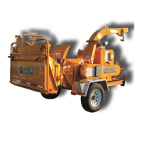
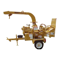
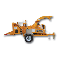
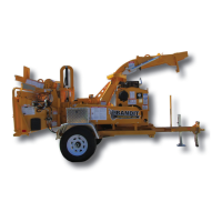
MODEL 20XP
First put control bar in o position.
2. Disconnect hose coming out of the port farthest from the handle of the control valve from the optional
motor or cylinder, and plug the hose.
Leave all other hydraulic hoses connected.
4. Install pressure gauge in the valve port which had the hose of the optional motor or cylinder disconnected.
5.
Start engine with the control bar in the o position.
Adjust engine to full throttle.
7. Only operate the valve for that component to activate pressure gauge. Pressure gauge should read the
maximum speci ed PSI (bar) for that component, see page 77.
ONLY OPERATE VALVE FOR 4-5 SECONDS TO SET PRESSURE OR YOU MAY DAMAGE
HYDRAULICS.
8. Readjust relief pressure setting if needed, if not needed, shut o engine and remove plug and pressure
gauge. Reassemble control valve to optional motor or cylinder.
Check for hydraulic leaks.
Relief valve pressure should be checked and/or readjusted every month for best performance.
PROCEDURE FOR CHECKING OPTIONAL HYDRAULIC COMPONENTS
Before attempting any hydraulic pressure settings, make sure engine is shut o , engine key removed and in
your possession, hydraulic oil is clean, hydraulic tank is 3/4 to 7/8 full, and the machine has been pre-run to
warm the hydraulic oil. To correctly check relief valve pressure, gauge
MUST be installed correctly.
WARNING
!
MAINTAIN HYDRAULIC PRESSURE AT SPECIFIED PSI (bar).
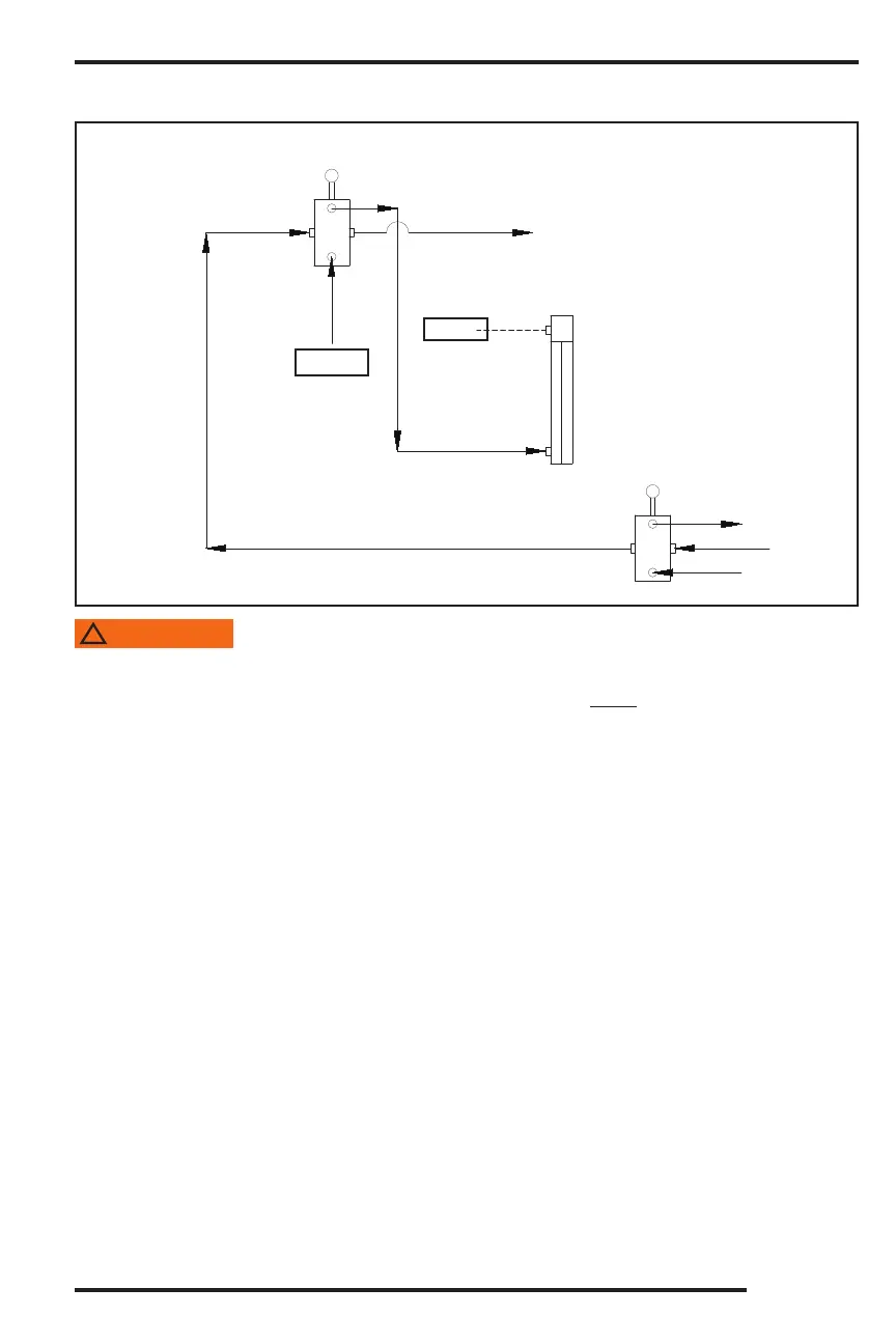
Yoke Lift
Cylinder
(OPTIONAL COMPONENT)
From
Pump
To Tank
Feedwheel
Control Valve
GAUGE
PLUG
YOKE LIFT CONTROL VALVE
ALL OPTIONAL COMPONENTS
MAY BE CHECKED THIS WAY
(VALVE FOR OPTIONAL
COMPONENT)
HYDRAULICS