Installation and connection
278 8LS...-3 user's manual V2.50
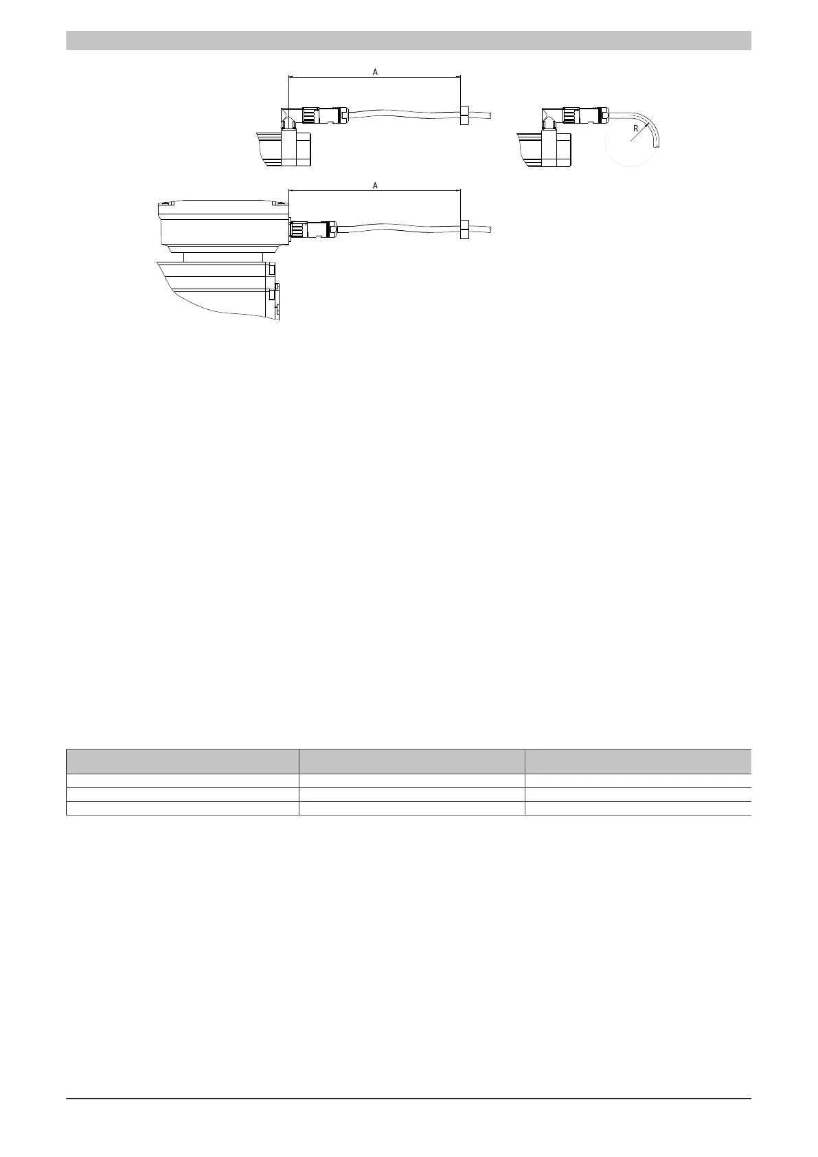
Cable clamp (A)
•
A = Max. 300 mm along longitudinal axis of connector
•
The connection must be free of force and torque.
•
Movement relative to the connector is not permitted!
•
Tensile stress on cables and connectors is not permitted!
Bend radius (R)
•
The minimum radius values can be taken from the current technical data sheet for the cable
5.5.1.4 Ring core design
Motors with shaft heights greater than 100 mm can already produce bearing currents that slowly damage the
bearing over a longer period of time. Bearing currents damage the bearing surfaces and are evident by a loud
running noise. This generally lasts 1-2 years. To ensure a long service life, B&R recommends analyzing for bearing
currents after the bearings have been in operation for a year. If necessary, contact B&R.
Dimensioning the ring core to avoid bearing currents
Different ferrite cores are necessary depending on the motor size and cable.
Since common-mode currents are heavily dependent on conditions, the following recommendations for ring core
dimensioning are only suggestions. In most cases, this dimensioning is sufficient.
The temperature of the ring cores can be measured to check whether the dimensioning is sufficient. If the temper-
ature is above 80°C, then one additional ferrite core of each respective type must be used.
Motor axis height (mm) M-112 ring core
Pieces
M-381 ring core
Pieces (for each phase)
100 1 1
132 2 1
160 3 2
Installation of the ring cores
Thread the 3 motor phases U, V and W together through the M-112 ring cores (1) and the individual phases U, V
and W each through the M-381 ring cores (2).
 Loading...