Self-Diagnostic Error Modes
In the unlikely event that the setup parameters are lost or become corrupt, the display will continuously scroll: “USEr PSF
Error.” Reteach the sensor to recover. If the problem persists, contact your Banner representative for further information.
Gate Input
The pink wire is configured as a gate input. When this wire is pulled low (for example, to the sensor ground; 0–0.5 V dc),
it inhibits the outputs from switching, while all other sensor functions continue to be enabled. This feature is useful for
controlling when the outputs are allowed to change states. Gate input function response time is 1 millisecond.
Specifications
Required Fiber-Optic Cable
Banner P-Series plastic fibers
Sensing Beam
Visible red, 680 nm or Visible green, 525 nm , depending on model
Supply Voltage and Current
12 to 24V dc (10% maximum ripple) at less than 65 mA, exclusive of
load
Supply Protection Circuitry
Protected against reverse polarity and transient voltages
Output Configuration
2 NPN or 2 PNP, depending on model
Output Rating
150 mA maximum load
OFF-state leakage current: < 10 μA at 24 V dc
ON-state saturation voltage:
NPN < 1.5 V at 150 mA load
PNP < 2.5 V at 150 mA load
Output Protection Circuitry
Protected against false pulse on power-up and continuous short-circuit
Output Response Time
Programmable, 50 microseconds, 200 microseconds, 1 millisecond, 2.5
milliseconds
NOTE: < 1 second delay on power-up;
outputs do not conduct during this time.
Adjustments
Push-button or remote programming of response time, OFF-delay,
light/dark operate, and display
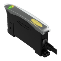
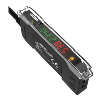
Indicators
Four-digit digital display plus LED indicators for active channel, push-
button lockout, OFF-delay and light/dark operate selection; 2 yellow
output indicators
Construction
Black ABS/polycarbonate alloy (UL94 V-0 rated) housing, clear
polycarbonate cover
Environmental Rating
NEMA 1, IEC IP50
Connections
PVC-jacketed 2 m or 9 m (6.5' or 30') 6-wire integral cable or integral
6-pin Pico-style quick-disconnect
Operating Conditions
Temperature: −20 °C to +55 °C (−4 °F to +131°F)
Storage Temperature: −20 °C to +80 °C (−4 °F to +176 °F)
90% at +50 °C maximum relative humidity (non-condensing)
Number of Devices,
Stacked
Ambient Temperature
Rating
Load Specification
3 55 °C 150 mA
7 50 °C 50 mA
10 45 °C 50 mA
Required Overcurrent Protection
WARNING: Electrical connections must be
made by qualified personnel in accordance
with local and national electrical codes and
regulations.
Overcurrent protection is required to be provided by end product
application per the supplied table.
Overcurrent protection may be provided with external fusing or via
Current Limiting, Class 2 Power Supply.
Supply wiring leads < 24 AWG shall not be spliced.
For additional product support, go to www.bannerengineering.com.
Supply Wiring (AWG)
Required Overcurrent Protection (Amps)
20 5.0
22 3.0
24 2.0
26 1.0
28 0.8
30 0.5
Certifications
D10 Expert
™
– Dual Discrete Outputs
14 www.bannerengineering.com - Tel: +1-763-544-3164 P/N 64154 Rev. G

 Loading...