Sensor Programming
Programming Procedures: Two push buttons, Dynamic (+) and Static (-), may be used to access and set programming
parameters. For remote programming, connect a switch or digital input to the gray wire; length of the individual pulses is
equal to the value T: 0.04 seconds ≤ T ≤ 0.8 seconds
Returning to RUN mode: TEACH and SETUP modes each may be exited in one of two ways: by exercising the 60-second
time-out, or by cancelling out of the process. In TEACH mode, the sensor will return to RUN mode without saving any of
the new settings; in SETUP mode, the sensor will return to RUN mode but save all of the settings. To cancel out of TEACH
mode, press and hold the Static (-) button for 2 seconds; to cancel out of SETUP mode, press and hold both the Static (-)
and Dynamic (+) buttons for 2 seconds.
Output 2: The setpoint(s) for each output can be set independently of one another (see Super-High Speed Operation).
However, the functional range available for output 2 is dictated by the automatic power and gain settings established for
output 1. Whenever output 1 is taught, output 2 also must be retaught. Applications hint: teach the weakest signal on
output 1 first.
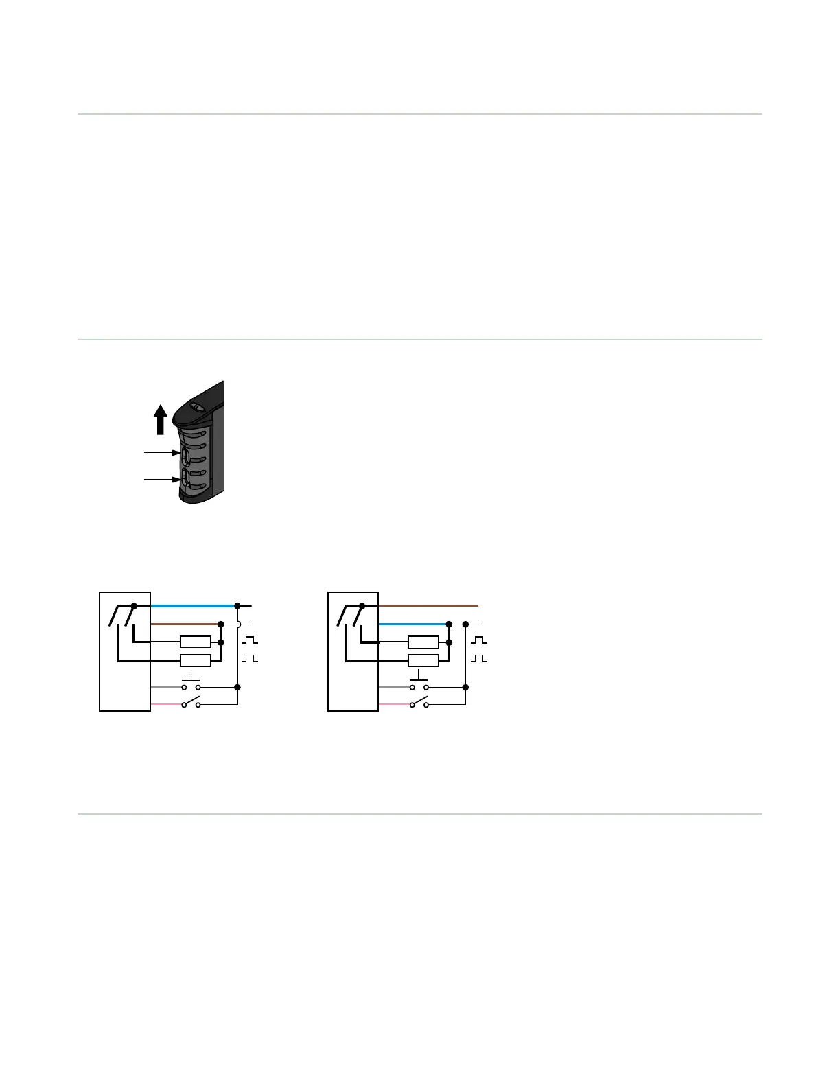
Installation
Install the product on a 35 mm DIN rail or the included mounting bracket.
Plastic Fiber
Emitter Port
Plastic Fiber
Receiver Port
Slides Up to
Release Fibers
Wiring Diagrams
NPN Output Models
3
1
4
5
6
2
12-24V dc
–
+
Load
Teach
Gate
Load
1
2
PNP Output Models
3
1
4
5
6
2
12-24V dc
–
+
Load
Teach
Gate
Load
1
2
Key
1 = Brown
2 = White
3 = Blue
4 = Black
5 = Gray
6 = Pink
Quick disconnect (QD) wiring diagrams are functionally identical.
Configuration Instructions
Active Channel Select
• Selects which channel to teach
• Displays channel configuration information.
D10 Expert
™
– Dual Discrete Outputs
P/N 64154 Rev. G www.bannerengineering.com - Tel: +1-763-544-3164 3

 Loading...