Returning to RUN mode: TEACH and SETUP modes each may be exited in one of two ways: by exercising the 60-second time-out, or by
cancelling out of the process. In TEACH mode, the sensor will return to RUN mode without saving any of the new settings; in SETUP mode,
the sensor will return to RUN mode but save all of the settings. To cancel out of TEACH mode, press and hold the Static (-) button for 2
seconds; to cancel out of SETUP mode, press and hold both the Static (-) and Dynamic (+) buttons for 2 seconds.
Output 2: The setpoint(s) for each output can be set independently of one another. However, the functional range available for output 2 is
dictated by the automatic power and gain settings established for output 1. Whenever output 1 is taught, output 2 also must be retaught.
Applications hint: teach the weakest signal on output 1 first. Output 1 sets the emitter power. If only output 2 will be used, output 1 must
be taught first. Or, enable tracking and teach only output 1, and then output 2 will be the same as output 1.
Dynamic TEACH and Adaptive Thresholds: Dynamic TEACH is used to program sensitivity during actual machine run conditions. During
Dynamic TEACH, the sensor takes multiple samples of the light and dark conditions and automatically sets the sensitivity at the optimum
level. For the discrete output, Dynamic TEACH activates the sensor’s adaptive threshold system, which continuously tracks minimum and
maximum signal levels, and automatically maintains centering of the switch point between the light and dark conditions. The adaptive
threshold system remains in effect during RUN mode to automatically adjust for changes in the light or the dark conditions.
When Dynamic TEACH mode is used to program sensitivity, the output ON state (light or dark operate) will remain as it was last
programmed. To change to either light or dark operate, use the SETUP mode (see Sensor Setup on page 10).
Sensitivity may be adjusted at any time when the sensor is in RUN mode by clicking the “+” and “-” buttons. However, when a manual
adjustment is made, the adaptive threshold system is disabled (cancelled).
Configuration Instructions
Analog Outputs
Output 1 is configured for either 4 to 20 mA or 0 to 10V dc analog output, depending on the model. The sensor may be programmed using
the two-point TEACH (either static or dynamic) or single-point window SET.
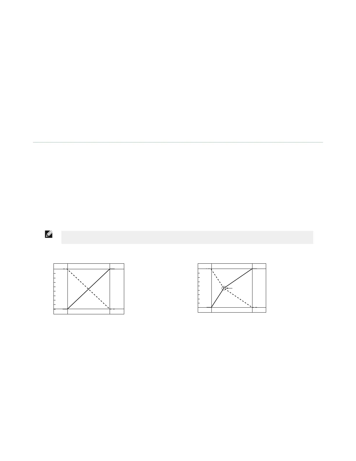
Two-point static or dynamic TEACH: The sensor sets the first taught condition to the highest output level (either 20 mA or 10V), and the
second taught condition to the lowest level (either 4 mA or 0V), and scales between these points. If the first condition taught has more
returned light, the sensor will be in Light Operate mode (LO). If the first taught condition is darker, the sensor will be in Dark Operate mode
(DO). To change the slope of the analog output (refer to Figure 2 on page 3), toggle LO/DO in Sensor Setup on page 10.
Single-point window SET: The sensor sets the taught condition to the mid-point of its range (12 mA or 5V, depending on the model). For
Light Operate mode, the sensor will automatically scale up to 20 mA (or 10V) for maximum light condition (the maximum possible received
signal) and down to 4 mA (or 0V) for maximum dark condition (no signal), and vice-versa for Dark Operate mode. To change the slope of
the analog output (refer to Figure 3 on page 3), toggle LO/DO in Sensor Setup on page 10.
An OFF-delay enabled for the analog output acts as an averaging function. During the OFF-delay period, the sensor will take multiple analog
readings and average the result before changing the analog value. This acts to reduce the effects of major spikes in the analog system, in
effect “smoothing” the output reading.
NOTE: Depending on the application configuration and fibers used, the analog function may or may not behave
linearly. The received light intensity will be dictated by the inverse square properties of light.
4 mA
20 mA
Dark Light
Signal
10V dc
0V dc
Voltage-Sourcing
Models
Current-Sourcing
Models
LO
Slope
DO
Slope
Figure 2. Analog output as a function of target position – two-point
static or dynamic TEACH
4 mA
20 mA
Max.
Dark
Max.
Light
Signal
10V dc
12 mA 5V dc
0V dc
Voltage-Sourcing
Models
Current-Sourcing
Models
LO
Slope
DO
Slope
Single Point
Taught
Figure 3. Analog output as a function of target position – window
SET
Active Channel Select
• Selects which channel to teach
• Displays channel configuration information.
D10 Expert
™
- Analog and Discrete Outputs
P/N 65448 Rev. G www.bannerengineering.com - Tel: +1-763-544-3164 3

 Loading...