• Adjusts sensing window size (tolerance) for the single-point target condition
• Press “+” to increase; press “-” to decrease
The lighted bar graph LEDs move to reflect the increase or decrease.
Enabling or Disabling the Push Button
In addition to its programming function, the remote line may be used to disable the push buttons for security. Disabling
the push buttons prevents undesired tampering with the sensor configuration settings.
1. Connect the sensor’s gray wire.
2. Four-pulse the remote line to enable or disable the push button.
The sensor toggles between enable and disable settings and returns to RUN mode.
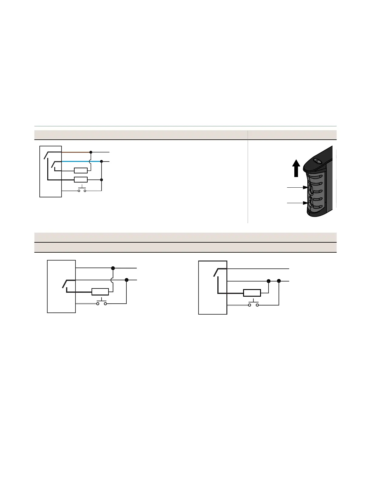
Wiring Diagrams
Standard Models and Main Unit Installing Fibers
3
1
2
4
5
10-30V dc Standard Models
12-30V dc Bussable Power Models
Remote Teach
150 mA max. load
Load
Load
+
−
1 - Brown
2 - White
3 - Blue
4 - Black
5 - Gray
6 - Pink (not used)
The QD hookup is functionally
identical. The pink wire is not used.
Plastic fiber
emitter port
Plastic fiber
receiver port
Slides up to
release fibers
Sub-Units
NPN PNP
5
4
Remote Teach
12-30V dc
Connection
From Main
Unit Bus
Load
+
−
5
4
Remote Teach
12-30V dc
Connection
From Main
Unit Bus
Load
+
−
D10 Expert
™
Series with Bar Graph Display and Discrete Output
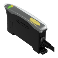
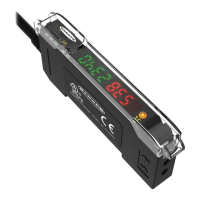
P/N 117830 Rev. G www.bannerengineering.com - Tel: +1-763-544-3164 9

 Loading...