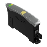
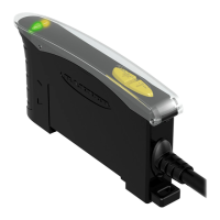
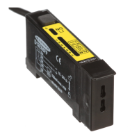
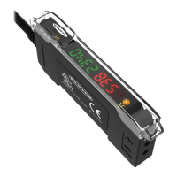
The sensor’s compact housing has a large, easy-to-see bar
graph display plus bright LEDs for easy programming and status
monitoring during operation.
Standard models have bipolar outputs, one each NPN and PNP.
Main units with bussable power have the same bipolar outputs;
sub-units feature a single discrete output, either NPN or PNP.
Models with bussable power are designed for use in machines
and other applications where multiple sensors will be grouped
tightly. They feature increased temperature compensation
compared with standard models and reduce the amount of
wiring necessary for such applications. An accessory clamp is
available to secure a bank of connected sensors together on a
DIN rail (see Accessories on page 13).
Power ON LED (green)
Configuration status
LEDs (green)
Bussable power input
port (cap supplied for
unused port)
Output LED (yellow)
Bar graph display (red)
Switching threshold
Configuration push buttons
Bussable power output
port (cap supplied for
unused port)
Figure 1. Features
Sensor Configuration
Sensor configuration is accomplished via TEACH, Set, and Setup modes. After the sensing parameters are defined (using
either TEACH or Set mode), Setup mode may be used to enable the delay, to change the light/dark operate status, or to
select the highspeed response option (HS). Manual Adjust may be used to fine-tune the thresholds. Two push buttons,
Dynamic (+) and Static (−), or the remote wire, may be used to access and set the sensing parameters.
Sensor sensitivity may be configured using any of three methods. A single switching threshold may be achieved using
either Dynamic (on-the-fly) or Static TEACH; or Window SET may be used to define a sensing window, centered on a
single sensing condition.
Remote Configuration
The remote configuration function may be used to configure the sensor remotely or to disable the push buttons for
security. Connect the gray wire of the sensor to ground (0V dc), with a remote programming switch connected between
them. Pulse the remote line according to the diagrams in the configuration procedures. The duration of the individual
pulses is equal to the value T: 0.04 seconds ≤ T ≤ 0.8 seconds
Returning to RUN Mode
Some TEACH, Set, and Setup modes may be exited either after the 60-second timeout, or by exiting the process:
• In Static TEACH or Window Set mode, press and hold the Static (−) button (or hold the remote line) for 2 seconds.
The sensor returns to Run mode without saving any new settings.
• In Setup mode, press and hold both the Static (−) and Dynamic (+) buttons (or hold the remote line) for 2
seconds. The sensor returns to Run mode and saves the current setting.
D10 Expert
™
Series with Bar Graph Display and Discrete Output
2 www.bannerengineering.com - Tel: +1-763-544-3164 P/N 117830 Rev. G

 Loading...


