Set Clear-State Light Level of Single-Point Window
Method Action Result
Push Button
1. Verify the fiber optic array is clean
and clear of any objects.
2. Press and hold Dynamic (+) button
for more than 2 seconds.
Display turns OFF and Arrow Icons 1 and 2 toggle 3 times
green while the sensor is optimizing system settings.
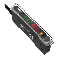
TEACH conditions acceptable:
• Display flashes “PASS”
• Sensor returns to Run mode with new settings.
• Arrow Icons 1 and 2 turn ON Green
• Health Mode output 2 Active
TEACH conditions unacceptable:
• Display flashes “FAIL”
• Arrow Icons 1 and 2 turn ON Red
• Health Mode output 2 Inactive
Remote Input
1. Make sure fiber optic array is clean
and clear of any objects.
2. Single-pulse the remote line.
Wiring Diagrams
Wiring for quick disconnect (QD) models are functionally identical.
NPN Output Models
PNP Output Models
bu
bn
wh
bk
gy
pk
load
−
+
12–24V dc
1
2
Teach
Gate
health
−
bn
bu
wh
bk
gy
pk
load
health
Teach
Gate
1
2
12–24V dc
+
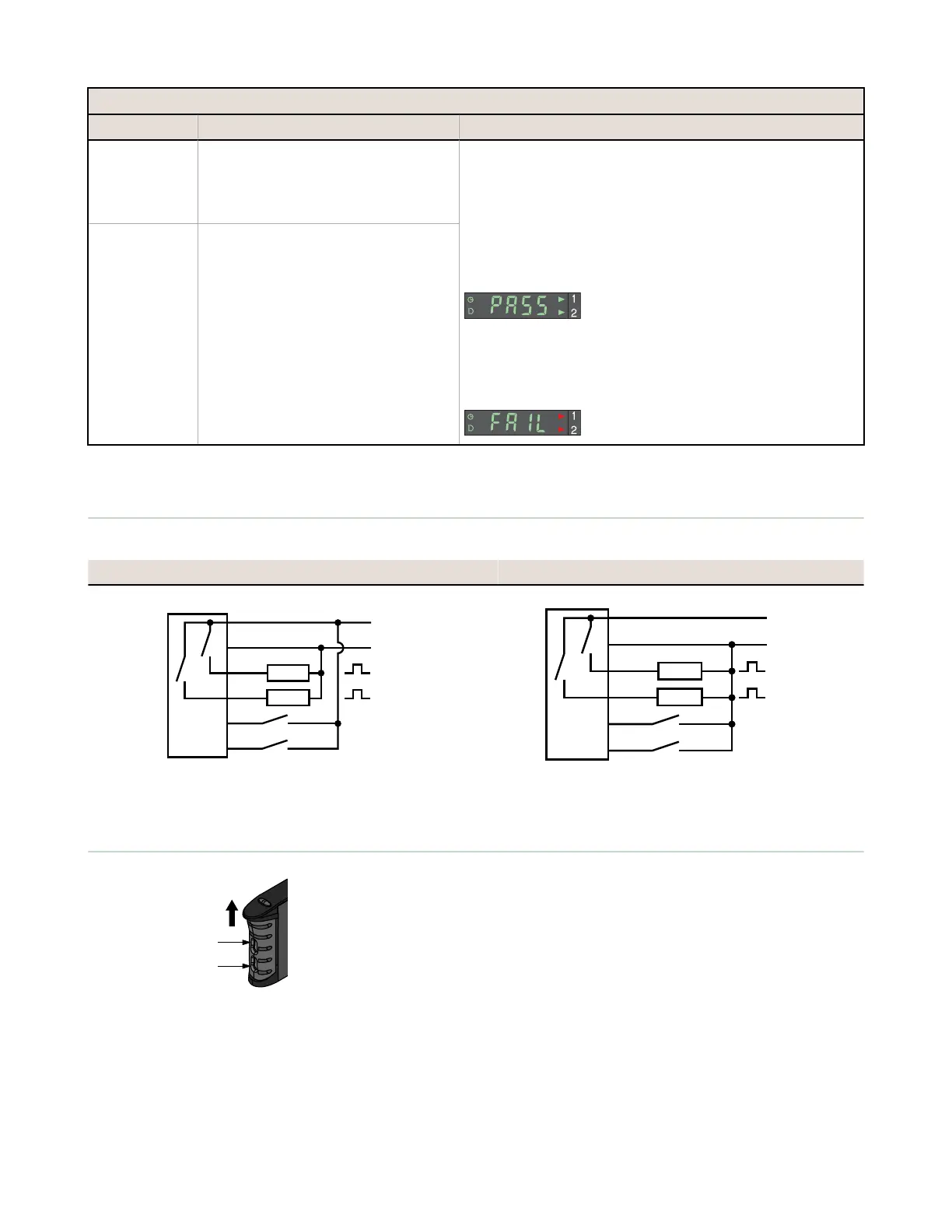
D10D...Port Locations
Plastic Fiber Emitter Port
Plastic Fiber Receiver Port
Slides Up to
Release Fibers
D10 Expert Series - Small Object Counter
8 www.bannerengineering.com - Tel: +1-763-544-3164 P/N 146132 Rev. D

 Loading...