1.2 Overview
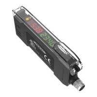
Figure 1. DF-G3 Single Output
Figure 2. DF-G3 Dual Output
1 Single Output LED or Dual Output LEDs
2
LO/DO Switch (Single Output) or CH1/CH2
Switch (Dual Output)
3 RUN/PRG/ADJ Mode Switch
4 Lever Acon Fiber Clamp
5 Red Signal Level
6 Green Threshold
7 +/SET/- Rocker Buon
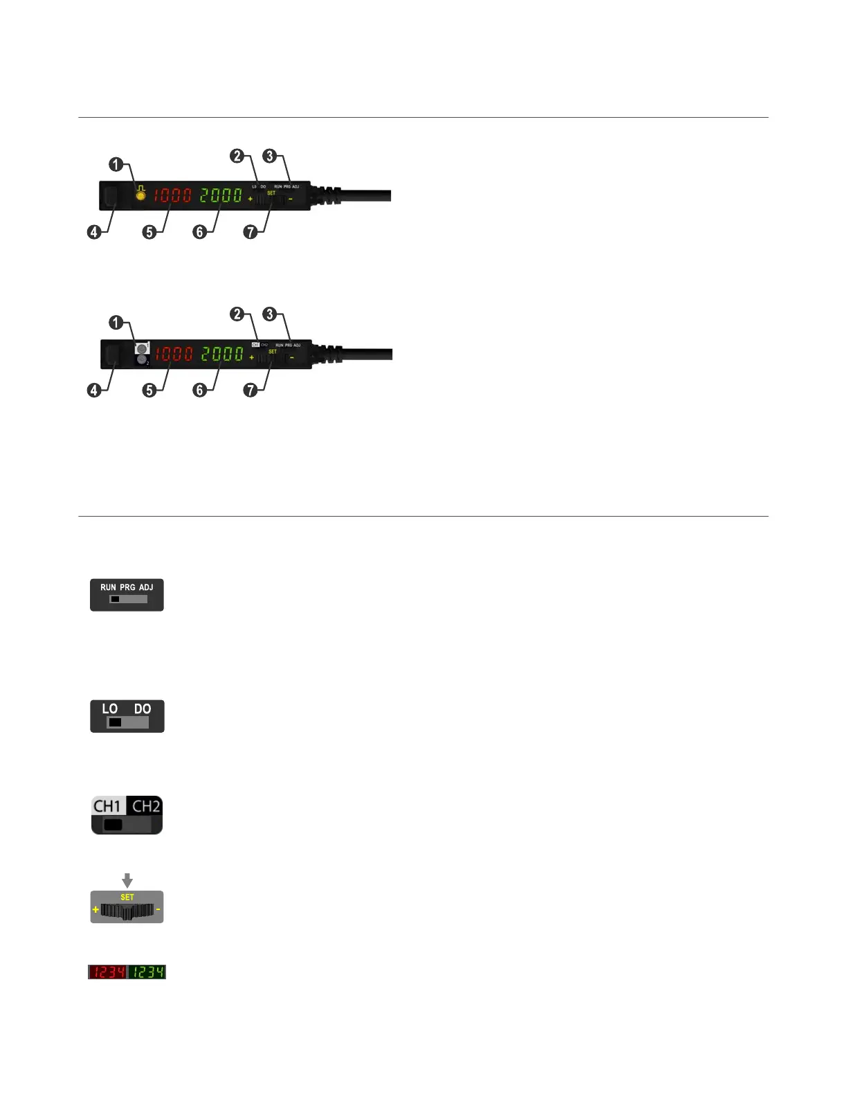
1.3 Top Panel Interface
Opening the dust cover provides access to the top panel interface. The top panel interface consists of the RUN/PRG/ADJ mode switch,
LO/DO or
CH1/CH2 switch, +/SET/- rocker buon, dual red/green digital displays, and output LED(s).
RUN/PRG/ADJ Mode Switch
The RUN/PRG/ADJ mode switch puts the sensor in RUN, PRG (Program), or ADJ (Adjust) mode.
•
RUN mode allows the sensor to operate normally and prevents unintenonal programming changes via
the +/SET/- rocker buon.
• PRG mode allows the sensor to be programmed through the display-driven programming menu (see
Program Mode
).
• ADJ mode allows the user to perform Expert TEACH/SET methods and Manual Adjust (see Adjust Mode on
page 16).
LO/DO Switch (Single Output Models)
The LO/DO switch selects Light Operate or Dark Operate mode.
•
In Light Operate mode, the output is ON when the sensing condion is above the threshold. (For Window
SET, the output is ON when the sensing condion is inside the window.)
•
In Dark Operate mode, the output is ON when the sensing condion is below the threshold. (For Window
SET, the output is ON when the sensing condion is outside the window.)
CH1/CH2 Switch (Dual Output Models)
The CH1/CH2 switch selects which output's parameters can be accessed and changed in the interface of the
display.
+/SET/- Rocker Buon
The +/SET/- rocker buon is a 3-way
buon. The +/- posions are engaged by rocking the buon le/right. The SET
posion is engaged by clicking down the buon while the rocker is in the middle posion. All three buon posions
are used during PRG mode to navigate the display-driven programming menu. During ADJ mode, SET is used to
perform TEACH/SET methods and +/- are used to manually adjust the threshold(s). The rocker buon is disabled
during RUN mode, except when using Window SET (see Window SET).
Red/Green Digital Displays
During RUN and ADJ modes, the Red display shows the signal level, and the Green display shows the threshold or
the total counts. During PRG mode, both displays are used to navigate the display-driven programming menu.
DF-G3 Long Range Expert
™
Dual Display Fiber Amplier
4 www.bannerengineering.com - Tel: 763.544.3164
 Loading...