1.2 Overview
The Q4X Sensor is a Class 1 laser CMOS sensor with a bipolar output. The normal sensor state is Run mode. From Run
mode, the switch point value and LO/DO selection can be changed and the selected TEACH method can be performed. The
secondary sensor state is Setup mode. From Setup mode, the TEACH mode can be selected, all standard operating
parameters can be adjusted, and a factory reset can be done.
1.3 Features
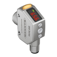
Figure 2. Sensor Features
1. Output Indicator (Amber)
2. Display
3.
Buttons
1.3.1 Display and Indicators
The display is a 4-digit, 7-segment LED. The main screen is the Run mode screen.
For 2-pt, BGS, FGS, and DYN TEACH modes, the display shows the current distance to the target in millimeters. For dual
TEACH mode, the display shows the percentage matched to the taught reference surface. A display value of
indicates the sensor has not been taught.
Figure 3. Display in Run Mode
1. Stability Indicator (STB—Green)
2. Active TEACH Indicators
•
DYN—Dynamic (Amber)
• FGS—Foreground Suppression (Amber)
• BGS—Background Suppression (Amber)
Output Indicator
•
On—Outputs conducting (closed)
•
Off—Outputs not conducting (open)
Active TEACH Indicators (DYN, FGS, and BGS)
• DYN, FGS, and BGS all off—Two-point TEACH mode
selected (default)
• DYN on—Dynamic TEACH mode selected
• FGS on—Foreground suppression TEACH mode
selected
• BGS on—Background suppression TEACH mode
selected
• DYN, FGS, and BGS all on—Dual TEACH mode
selected
Stability Indicator (STB)
•
On—Stable signal within the specified sensing range
• Flashing—Marginal signal, the target is outside the
limits of the specified sensing range, or a multiple
peak condition exists
• Off—No target detected within the specified sensing
range
1.3.2 Buttons
Use the sensor buttons (SELECT)(TEACH), (+)
(DISP), and (-)(MODE) to program the sensor.
Q4X Stainless Steel Laser Sensor
4 www.bannerengineering.com - Tel: 763.544.3164
 Loading...