3. Check the sensor alignment.
4. Tighten the mounting screws to secure the sensor (or the sensor and the bracket) in the aligned position.
2.4 Wiring Diagram
—Threaded Barrel Models
3
1
2
4
5
10-30V dc
Remote
T
each
Load
Load
+
–
NOTE: Open lead wires must be connected to a terminal block.
Key
1 = Brown
2 = White
3 = Blue
4 = Black
5 = Gray
NOTE: The input wire function is user-selectable. The default for the input wire function is off (disabled).
2.5 Wiring Diagram—Flush Mount Models
NPN Models
PNP Models
Key
1 = Brown
2 = White
3 = Blue
4 = Black
NOTE: Open lead wires must be connected to a terminal block.
NOTE: The input wire function is user-selectable. The default for the input wire function is off (disabled).
2.6 Cleaning and Maintenance
Handle the sensor with care during installation and operation. Sensor windows soiled by fingerprints, dust, water, oil, etc.
may create stray light that may degrade the peak performance of the sensor. Blow the window clear using filtered,
compressed air, then clean as necessary using water and a lint-free cloth.
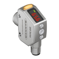
Q4X Stainless Steel Laser Sensor
www.bannerengineering.com - Tel: 763.544.3164 7
 Loading...