NE134
www.baumer.com
29
The user must take care that, in case of disturbance, the contact
rating of 8 A / 150 VA (W) is not exceeded. The output relay of the
instrument (1 relay or more) may, in total, switch max. 5 x per mi-
nute. Admissible clicks as per interference suppression standards
EN 61000-6-4 for the industrial sector. In case of higher switching
rate, the user is responsible for and in charge of providing interfe-
rence protection on site in consideration of the load to be switched.
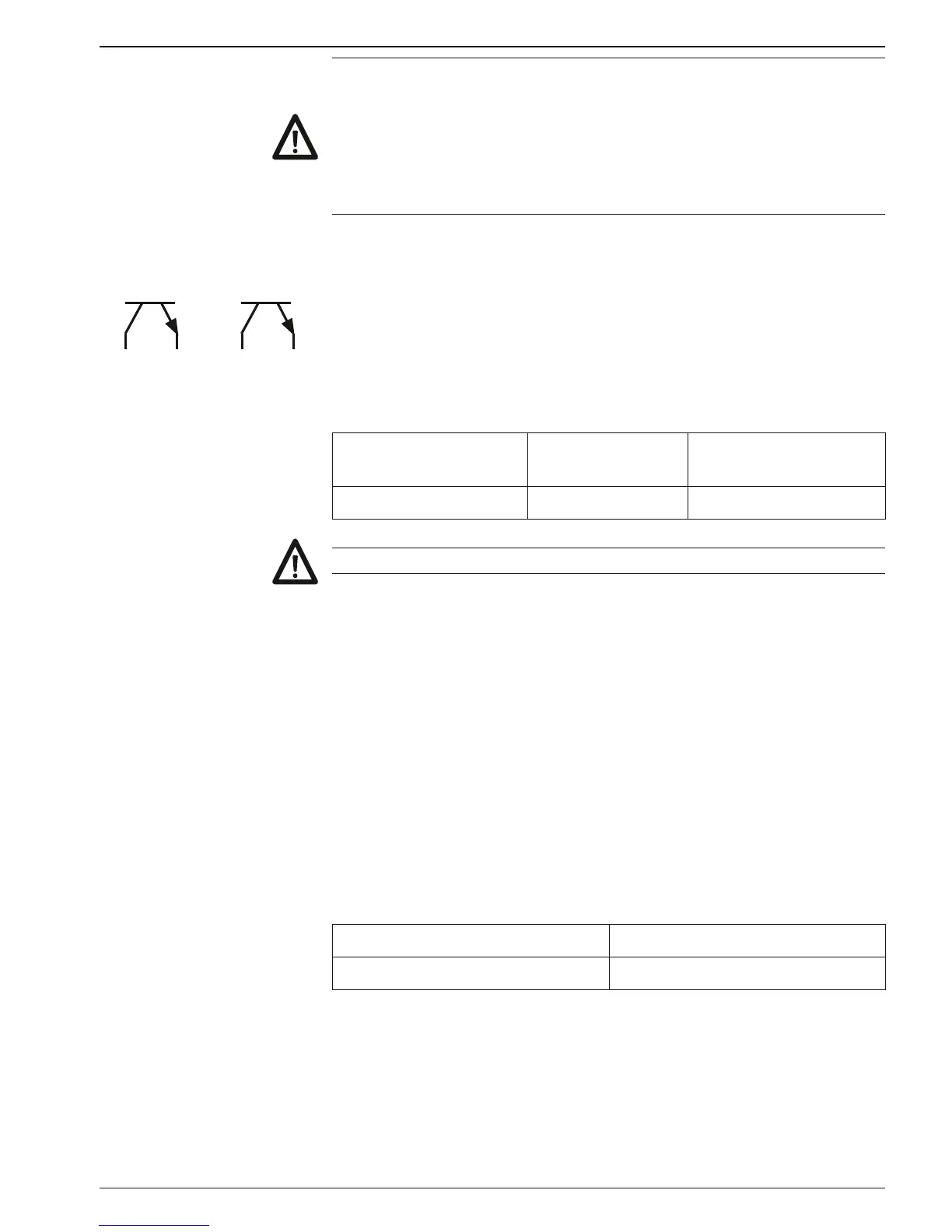
3.3 Assignment of signal outputs (electronic)
4 36 5
Output P2 Output P1 The electronic outputs (contacts 3, 4 and 5, 6) are optocoupler
outputs. The signal outputs can be assigned as per the adjacent
terminal diagram.
The type of outputs, as momentary or latched signal, can be cho-
sen in the programming lines 41/42.
Their function, as normally open or closed, is selected in program-
ming line 40.
Max. switching
voltage
Max. switching
current
Max. residual voltage
+40 VDC 25 mA at 25 mA <1 V
The electronic outputs are not short-circuit-proof.
3.4 Assignment of signal inputs
Choics of PNP or NPN The contacts 7 to 11 are comparator signal inputs.
They can be triggered either by PNP or NPN encoders. The input lo-
gic as well as the operating threshold are correspondingly chosen
in programming line 33. The contacts 7 (Track A) and 8 (Track B) are
counting inputs for a counting range between 3 Hz, 25 Hz or 10 kHz.
The counting rate is determined in programming lines 31 and 32.
The contacts 9, 10 and 11 are 3 control inputs for Reset, Stop, Hold,
Print, Keylock etc. The function of these control inputs is selected in
the programming lines 34, 36 and 37.
The minimum pulse duration of control input 1 can be switched in
programming line 35 from 30 ms to 100 μs. For control inputs 2 and
3, 30 ms are generally valid.
Input resistance Selectable operating threshold
approx. 3 kΩ 3 V and 6 V