NE134
30 www.baumer.com
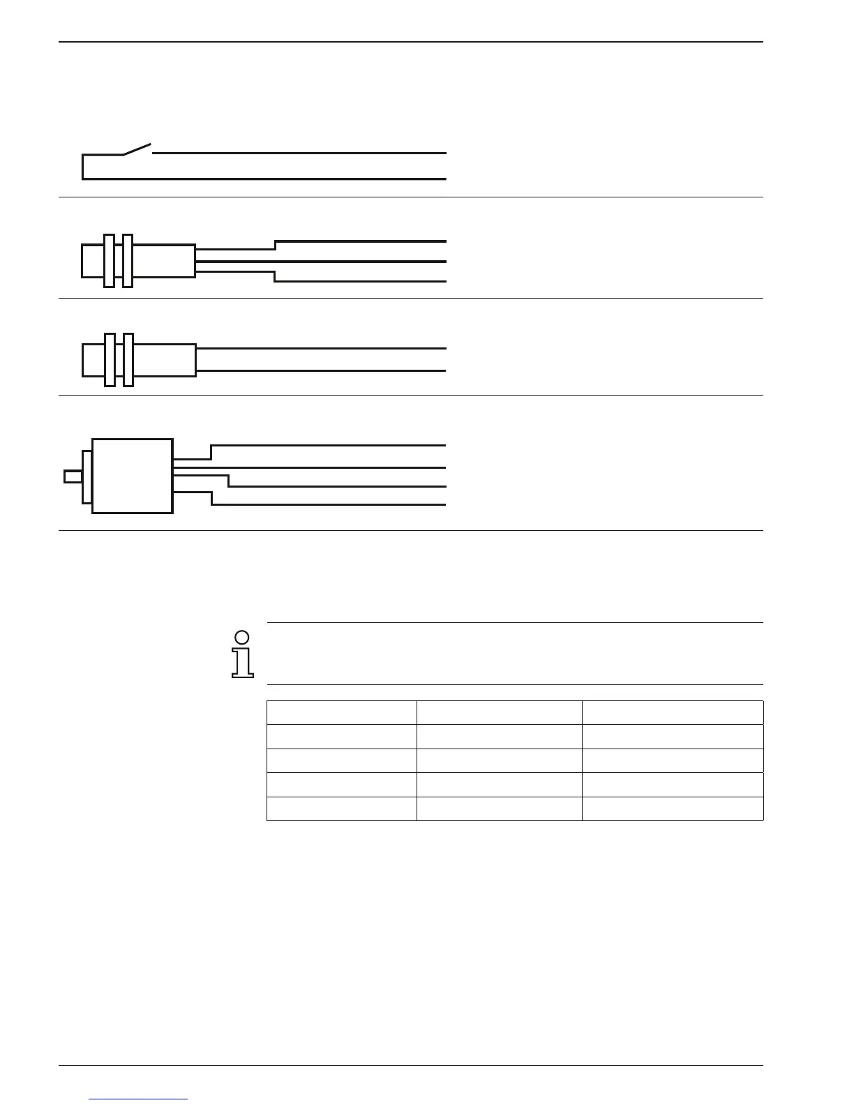
3.5 Examples of connection
Sensor Contact assignment Programming
Contact
7
12
Track A
+24 V
Counting rate:
Line 31 to 1 = 25 Hz
Line 31 to 2 = 3 Hz
Proximity switch PNP or NPN
7
12
13
Track A
+24 V
0 V
Input logic:
Line 33 to 0 = PNP
Line 33 to 1 = NPN
Namur without ex. protection
7
13
Track A
0 V
Input logic:
Line 33 to 1 = NPN
Incremental encoder
7
8
12
13
Track A
Track B
+24 V
0 V
Counting mode
A 90° B (x1, x2, x4)
Line 30 to 3, 4, 5
Count frequenz:
Line 31, 32 to 0 = 10 kHz
3.6 Sensor supply connection
Connect the sensor supply at terminals 12 and 13 – for example en-
coder supply, etc.
Do not use the sensor supply to supply non-earthed inductive or
capacitive loads. The sensor supply is short-circuit proof (exception
model 24/48 VAC).
Voltage supply Sensor supply Current load
24 VAC 10...26 VDC 60 mA
48 VAC 10...26 VDC 60 mA
85...265 VAC 24 VDC ±20 % 100 mA
12...30 VDC 9...28 VDC ±20 % 100 mA
3.7 RS485 interface connection
The serial interface can perform the following functions:
- retrieve data
- program parameters
Interface parameters are:
- transmission speed (baud rate),
- parity bit,
- number of stop bits,
- address of controller for master.