NE134
www.baumer.com
41
5.3 Output (output mode)
The behavior of the signal outputs is defined by the following set-
tings under the programming field 3: Operating mode, preset mode,
reset mode, take-over of presets, output logic and output time P1
and P2 as momentary
or latched signal .
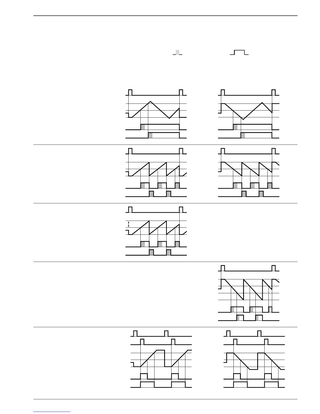
The following diagrams illustrate some examples:
Programming Operating mode:
Line 21 at 0 = adding
Operating mode:
Line 21 at 1 =subtracting
Preset mode:
Line 22 to 0 = Progressive
preset
Reset mode: Line 23 to 1 or
3 without automatic reset
Output time P1, P2: Line 41,
42 to pulse or duration
VW (P2)
VW (P1)
O (SC)
OUT P1
Preset mode:
Line 22 to 0 = Progressive
preset
Reset mode: Line 23 to 0 =
automatic
VW (P2)
VW (P1)
O (SC)
OUT P1
Preset mode:
Line 22 to 1 = Trailing preset
VW (P1) corresponds to the
interval between P1 and P2.
When P2 is changed, P1 is
trailed.
VW P1
Operation mode:
Line 21 to 2 = OUT P2 at SC,
automatic reset at 0
Preset mode:
Line 22 to 0 = Progressive
preset
Preset mode:
Line 22 to 0 = Progressive
preset
Reset mode: Line 23 to 1 or
3 without automatic reset
Function control input 2: Line
36 to 7 = OUT P1 and OUT
P2 are activated by a signal
to control input 2 (Ein St2).