Syscompact 2000 M pro Cable fault pre-location
822-175-2 53 / 98
12.3 TDR: Time Domain Reflectometry
12.3.1 About the TDR method
Areas of application
To detect the cable length and to test the velocity of propagation
To check if all phases are equal in length and if there is a cable break
To detect joints and other impedance changes
To compare healthy and faulty phases
Measurement principle
A transmitting pulse is fed into the cable. When the transmitting pulse reaches a position with
impedance change (cable ends, faults or joints), a part of the pulse energy is reflected to the
time domain reflectometer. These reflections are recorded and presented in a graph.
The amplitude of a reflection is determined by the extent of the impedance change, which is
defined by the reflection factor r:
Cable impedance up to impedance change
Impedance of a change in the cable route (e.g. fault or joint)
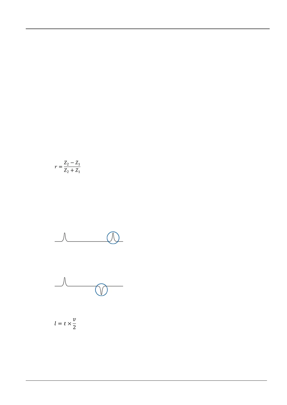
If the impedance of a change Z
2
is greater than the cable impedance Z
1
, the reflection factor is
positive. In the reflection image, the open cable end is displayed by a positive reflection.
If the impedance of a change Z
2
is less than the cable impedance Z
1
, the reflection factor is
negative. In the reflection image, a short-circuit or a low-resistive fault is displayed by a
negative reflection:
To determine the fault distance, the time gap between the transmitting pulse and the reflecting
pulse is measured. The fault distance is calculated with the following formula.
Time gap between the transmitting pulse and the reflecting pulse