Syscompact 2000 M pro Cable fault pre-location
822-175-2 59 / 98
Saving measurement data
Measurement data comprise: Trace incl. set parameters, date and time of the measurement
and cursor positions.
1. To save the measurement data, press the FUNCTION key after the evaluation.
2. Use the rotary knob to select the button and press the rotary knob.
The measurement data are saved.
The measurement data can be transferred to a PC or laptop and printed. To do so, the IRG
2000 must be removed from the system.
Further information:
Chapter Printing measurement data (on page 45)
User manual for IRG 2000
12.4 SIM/MIM: Secondary-Multiple Impulse Method
12.4.1 About the SIM/MIM method
The secondary-multiple impulse method (SIM/MIM) is the most well-established and precise
pre-location method and in most cases, performs fast fault pre-location. It is used for
pre-locating high-resistive faults.
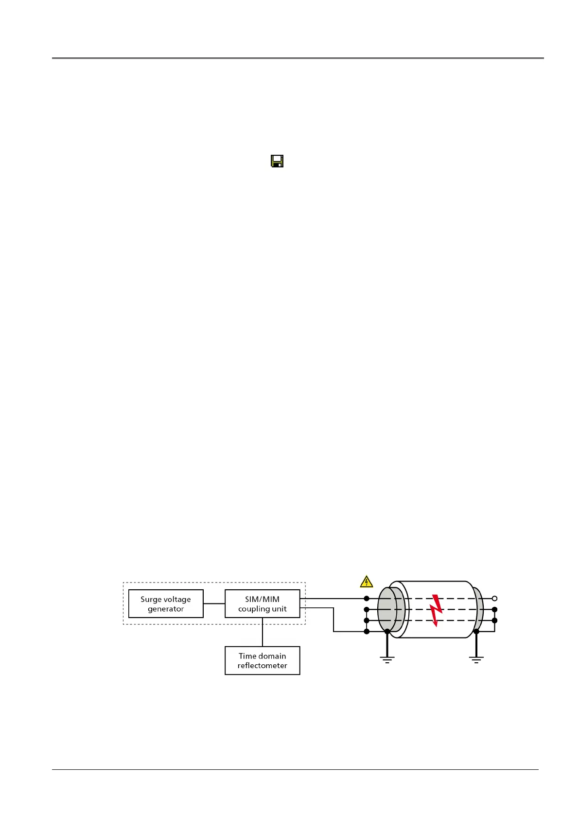
The SIM/MIM method is based on the electric arc surge method. With this method, first a
reflection image is recorded without a fault or with a high-resistive fault. As high-resistive faults
result in very minor or no impedance changes at the fault position, no fault is visible on this
reflection image. Therefore, it is also called “healthy trace”. Then, a HV surge pulse is fed into
the defective cable (phase), which ignites an electric arc at the fault position and temporarily
converts the fault into a low-resistive connection. Precisely at the time of the ignition, reflection
measurements are completed. Thereby, LV pulses are fed into the cable, which are reflected
negatively at the temporary low-resistive fault. The reflection image is displayed on screen
without and with an electric arc. The fault position at the negative reflection is clearly visible by
comparing the reflection images. The fault distance is calculated from the duration of the pulse
and the velocity of propagation (v/2).
The breakdown time can be delayed or the duration of the breakdown can be shorter due to
the varying properties of the cable fault. With the four automatic reflection measurements, you
are assured that the right time when the fault becomes low-resistive will be recorded. The 4
reflection measurements are performed from a measurement range of 1024 m upwards.
Main circuit diagram