EasyManuals Logo

Baxi POWER HT+ Series Installation And Service Manual

Baxi POWER HT+ Series
124 pages
To Next Page IconTo Next Page
To Previous Page IconTo Previous Page
Page #108 background imageLoading...
Page #108 background image
S
See
Accessing the internal boiler components, page 37.
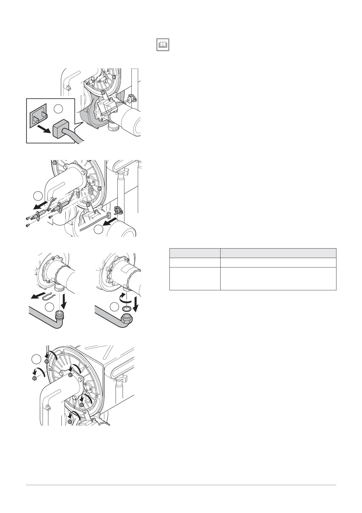
5. Disconnect the power and command cables on the fan.
6. Disconnect the ignition electrode, the safety thermostat and the
flame detection sensor.
7. Remove the pipe connecting the gas valve to the Venturi unit.
Reference Model
A
POWER HT+ 1.50
B
POWER HT+ 1.70
POWER HT+ 1.90
POWER HT+ 1.110
8. Remove the nuts holding the burner in place on the heat exchanger.
Fig.
135
Removing the cables from the fan
MW-3000127-01
5
Fig.
136
Removing the cables from the elec
trode, the thermostat and the sensor
MW-3000128-01
6
6
Fig.
137
Removing the connection pipe
7
MW-3000107-01
7
AB
Fig.
138
Removing the retaining nuts
MW-3000108-01
8
10 Maintenance
108 7609474 - v02 - 04092014

Table of Contents

Other manuals for Baxi POWER HT+ Series

Questions and Answers:

Question and Answer IconNeed help?

Do you have a question about the Baxi POWER HT+ Series and is the answer not in the manual?

Baxi POWER HT+ Series Specifications

General IconGeneral
ModelPOWER HT+ Series
CategoryBoiler
Installation TypeWall-mounted
Heat Exchanger MaterialStainless Steel
Warranty2 years
Fuel TypeNatural Gas
Control SystemIntegrated Control
Ignition TypeElectronic

Related product manuals