7
7.4.3 Setting the air/gas ratio (reduced thermal flow rate)
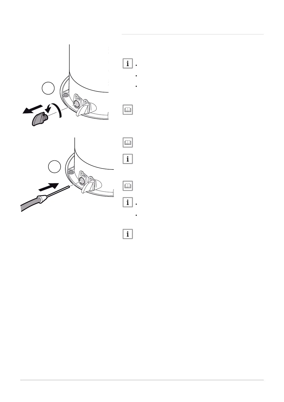
1. Unscrew the left-hand plug, which corresponds to the flue gas
measurement point connection.
2. Connect the flue gas analyser to the connection on the left.
Ensure that the opening around the sensor is completely sealed
when taking measurements.
Insert the sensor into the flue gas measurement point opening
to at least 8 cm for POWER HT+ 1.50 and POWER HT+ 1.70.
Insert the sensor into the flue gas measurement point opening
to at least 9 cm for POWER HT+ 1.90 and POWER HT+ 1.110.
3. Set the boiler's thermal flow rate to 0%.
Using the boiler according to thermal output, page 94
4. Measure the percentage of CO
2
in the flue gases.
5. Compare the values measured with the set point values in the Con
trol and setting values table.
CO2 checking and setting values, page 62
A tolerance of +/- 0.5% is acceptable.
6. If necessary, adjust the air/gas ratio using the OFFSET adjustment
screw.
Gas valves, page 62.
Turn the gas adjustment screw clockwise to increase the CO
2
content.
Turn the gas adjustment screw counter-clockwise to reduce the
CO
2
content.
A tolerance after adjustment of +/- 0.2% is acceptable, when the
front door is removed.
Fig.65 Connecting the flue gas analyser
MW-3000046-01
2
1
7 Commissioning
7609474 - v02 - 04092014 61

 Loading...


