Tab.25 Checking and setting values for gas type G25
U
Unit POWER HT+ 1.50 POWER HT+ 1.70 POWER HT+ 1.90 POWER HT+ 1.110
Diameter of the Venturi mm 24 30 34 38
Diameter of the nozzles mm 4.20 (no. 2) Variable mixer
nozzles: top part
with a diameter of
5.70 mm, bottom
part with a diame
ter of 6.50 mm.
6.30 (no. 2) Variable mixer noz
zles: top part with a
diameter of 6.80
mm, bottom part
with a diameter of
7.70 mm.
Minimum CO
2
(1)
% 8.5 8.6 8.6 9.0
Maximum CO
2
(1)
% 8.9 8.9 8.8 9.1
Maximum CO ppm < 250 < 250 < 250 < 250
Tab.26 Checking and setting values for gas type G31
Unit POWER HT+ 1.50 POWER HT+ 1.70 POWER HT+ 1.90 POWER HT+ 1.110
Diameter of the Venturi mm 24 30 34 38
Diameter of the nozzles mm 2.95 (no. 2) 4.0 (no. 2) 4.5 (no. 2) 5.0 (no. 2)
Minimum CO
2
(1)
% 9.5 9.5 9.9 9.5
Maximum CO
2
(1)
%10 10 10 10
Maximum CO ppm < 250 < 250 < 250 < 250
7.4.6 Adapting to another gas type
Caution
Only a fully trained, qualified professional may carry out the follow
ing operations.
The boiler is pre-set in the factory to run on natural gas H
.
Conversion kits are available for other types of gas G
and G
.
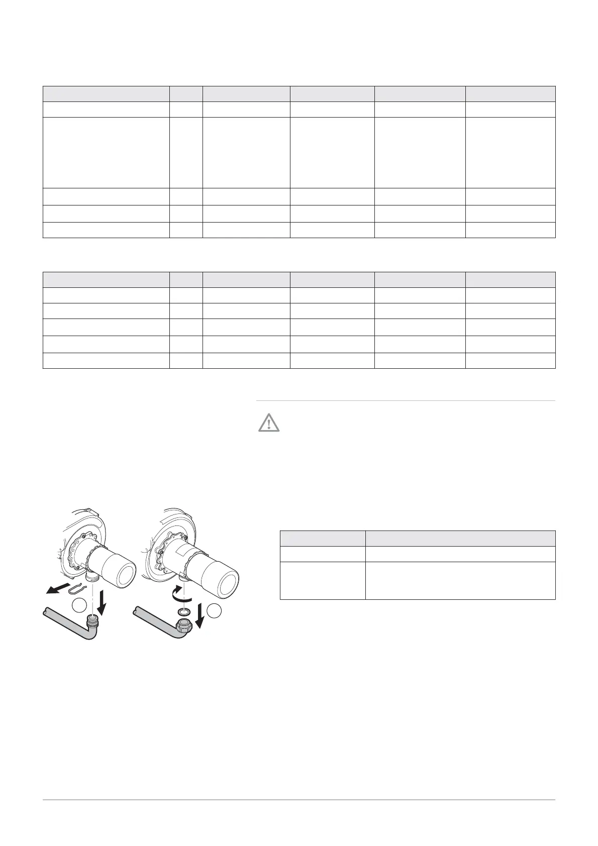
1. Close the mains gas valve.
2. Remove the pipe connecting the Venturi to the gas valve.
Tab.27 Connection differences
POWER HT+ 1.50
POWER HT+ 1.70
POWER HT+ 1.90
POWER HT+ 1.110
Fig.68 Removing the connection pipe
MW-3000048
A
2
2
B
7 Commissioning
7609474 - v02 - 04092014 63

 Loading...


