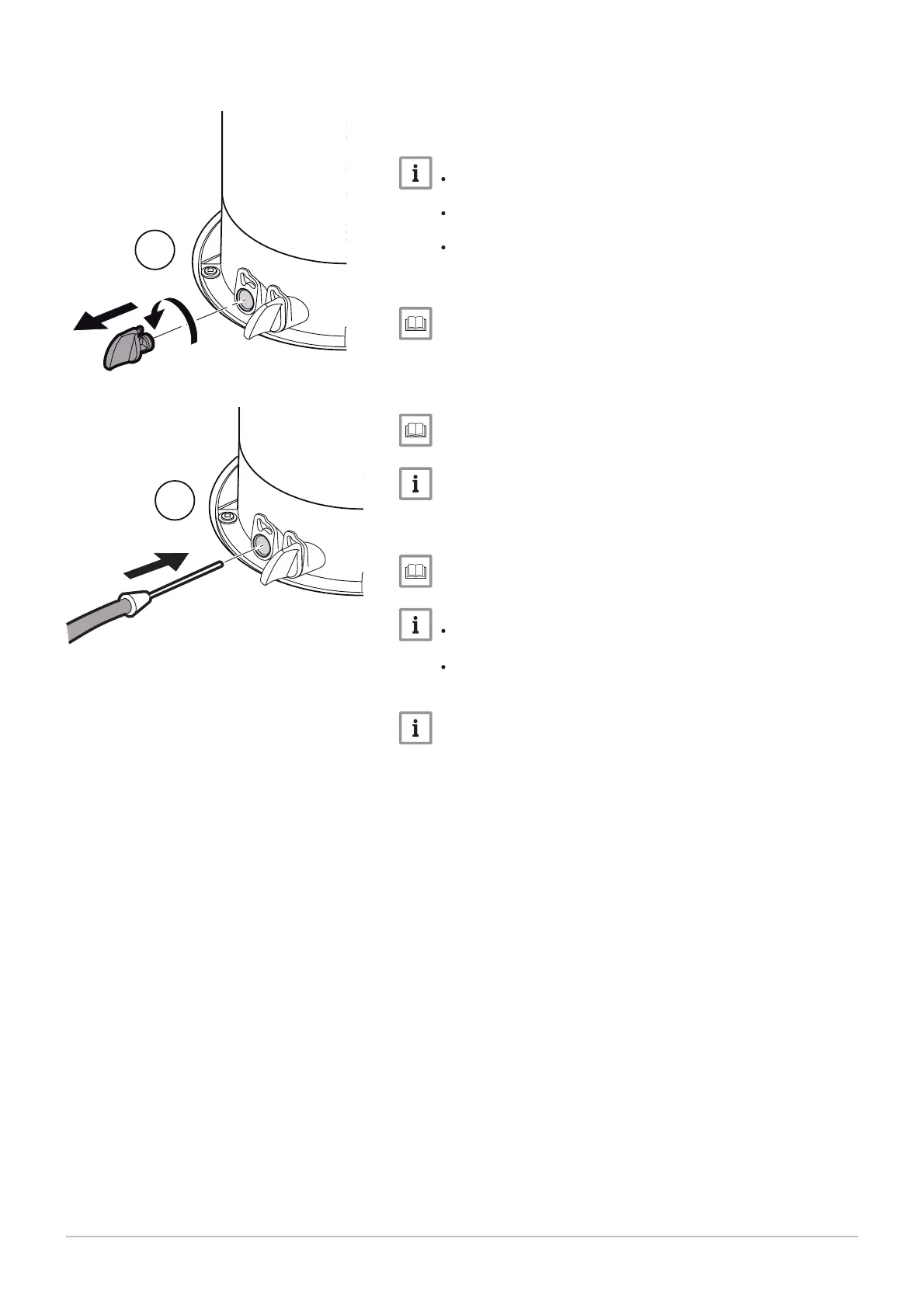
1. Unscrew the left-hand plug, which corresponds to the flue gas
measurement point connection.
2. Connect the flue gas analyser to the connection on the left.
N
Ensure that the opening around the sensor is completely sealed
when taking measurements.
Insert the sensor into the flue gas measurement point opening
to at least 8 cm for POWER HT+ 1.50 and POWER HT+ 1.70.
Insert the sensor into the flue gas measurement point opening
to at least 9 cm for POWER HT+ 1.90 and POWER HT+ 1.110.
3. Set the boiler's thermal flow rate to 100%.
Using the boiler according to thermal output, page 94.
4. Measure the percentage of CO
2
in the flue gases.
5. Compare the values measured with the set point values in the Con
trol and setting values table.
CO2 checking and setting values, page 62
A tolerance of +/- 0.5% is acceptable.
6. If necessary, adjust the air/gas ratio using the gas flow rate adjust
ment screw.
Gas valves, page 62.
Turn the gas adjustment screw clockwise to reduce the CO
2
content.
Turn the gas adjustment screw counter-clockwise to increase
the CO
2
content.
A tolerance after adjustment of +/- 0.2% is acceptable, when the
front door is removed.
Fig.64 Connecting the flue gas analyser
MW-3000044-01
1
2
7 Commissioning
60 7609474 - v02 - 04092014

 Loading...


