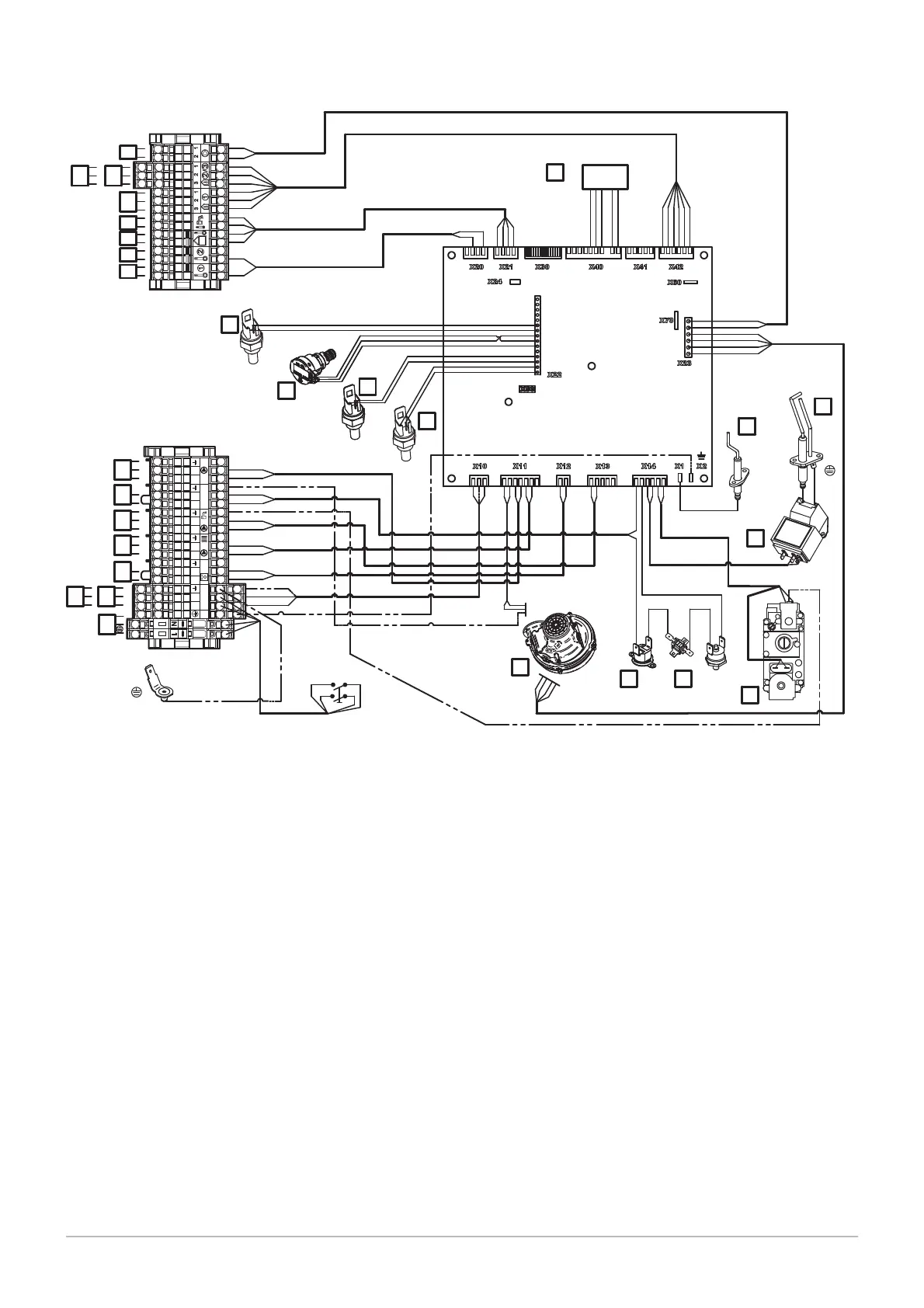
Fig.5 Electrical diagram POWER HT+ 1.90 – POWER HT+ 1.110
1
2
3
4
Aux 1-2 230 V
TA TS
LN LN L LNNLNLN
O
N
P
M
L
K
J
I
H
G
F
E
L
N
A
C
B
D
3
4
1A
2A
1
1
2
2
11
10 12
9
8
7
6
1
2
3
4
HMI
5
MW-3000004-01
A
Power supply 230V 50Hz
Power supply auxiliary circuit 1
Power supply auxiliary circuit 2
Room thermostat
Heating circuit pump
Domestic hot water pump
Safety contact
Boiler pump
Auxiliary sensor 1
Auxiliary sensor 2
Outside temperature sensor
Domestic hot water sensor
Room temperature sensor 1
Room temperature sensor 2
Room temperature sensor 3
Boiler pump modulation (PWM)
Flow temperature sensor
Return sensor
Hydraulic pressure sensor
Flue gas sensor
HMI Text display
Ionisation probe
Spark plug
Igniter
Gas valve
Safety thermostat
Fan
Thermal fuse
Safety thermostat on the combustion chamber door
3 Technical specifications
16 7609474 - v02 - 04092014

 Loading...


