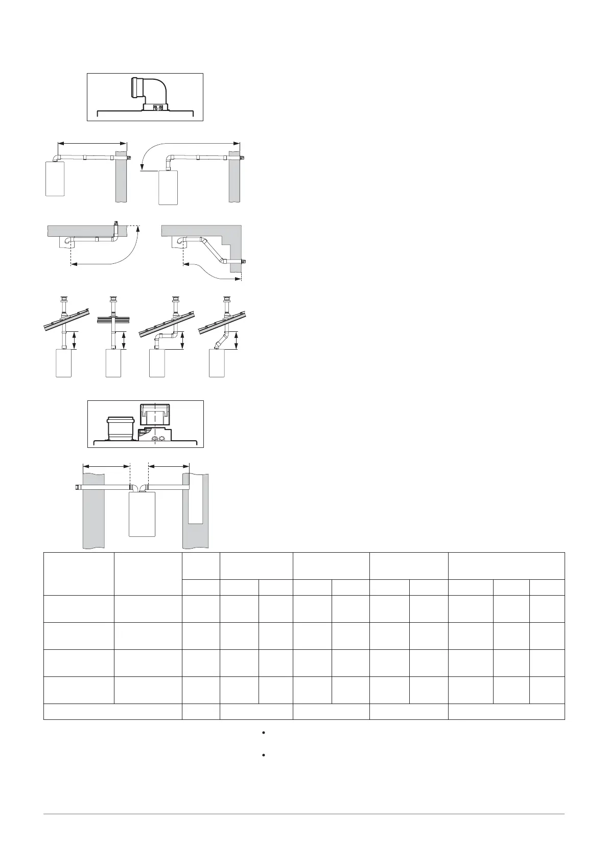
Tab.17 Flue gas system connection type B23p
Arrangement Configuration Unit POWER HT+
1.50
POWER HT+
1.70
POWER HT+
1.90
POWER HT+ 1.110
mm Ø 80 Ø 110 Ø 80 Ø 110 Ø 110 Ø 125 Ø 110 Ø 125 Ø 160
L3<2m + 2 el
bows
(L1 + L2) rigid m 20 56 8 56 20 56 56 56 –
L3<2m + 2 el
bows
(L1 + L2) flexi
ble
m 15566 38– 2115 – –
L3<5m + 2 el
bows
(L1 + L2) rigid m – 56 – 56 24 56 – 43 56
L3<5m + 2 el
bows
(L1 + L2) flexi
ble
m– 56– 3813– – – –
Pressure available at blow back Pa 200 200 200 200
Ventilation of the premises: In accordance with the standard NFP 45 –
204 or DTU 61.1
Lengths L1, L2 and L3 are obtained with Centrovec pipes covered by
CE marking and the TAD Technical Application Directive.
Fig.50 Maximum length of the connections
MW-3000033
1
34
LL
L1
L2
L
L L
L
L
L
578
6
9
2
6 Installation
7609474 - v02 - 04092014 47

 Loading...


