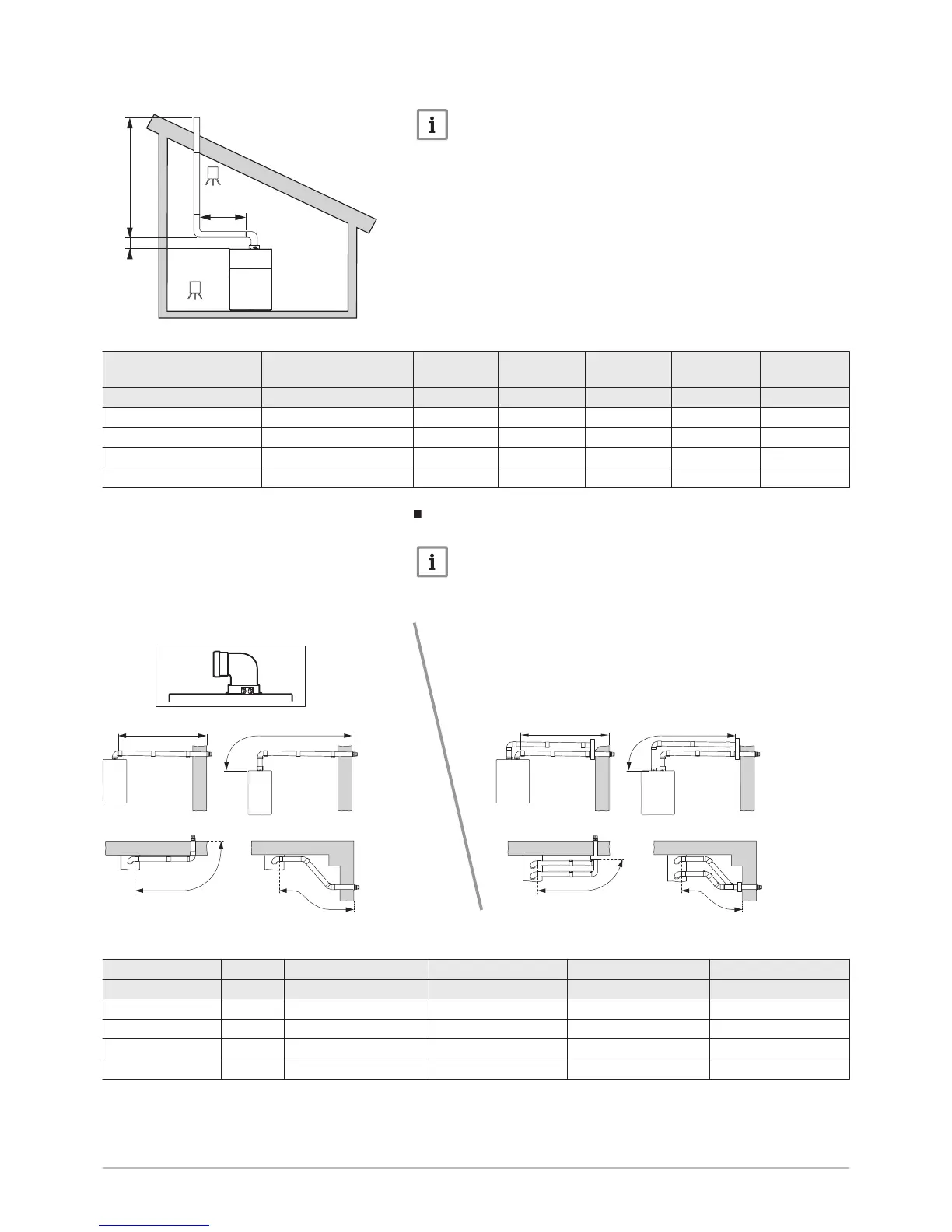
Important
For B
23p
configurations, the lengths given in the tables are valid
for horizontal pipes with a maximum length of 1 metre. For each
additional metre of horizontal pipe, subtract 1.2 m from the vertical
length L
max
.
Tab.20 Flue gas system connection type B
23p
Arrangement Configuration Unit POWER HT
+ 1.130
POWER HT
+ 1.150
POWER HT+
1.200
POWER HT+
1.250
mm Ø 110 Ø 110 Ø 160 Ø 160
L3<2m + 2 elbows (L1 + L2) rigid m 20 27 39 23
L3<2m + 2 elbows (L1 + L2) flexible m 7 9 19 13
L3<5m + 2 elbows (L1 + L2) rigid m 17 23 36 19
L3<5m + 2 elbows (L1 + L2) flexible m - 6 15 10
Configuration C
13
Important
Pipes subject to technical evaluation 14 08–1289.
Fig.77
Tab.21 Maximum length for configuration C
13
Configuration Unit POWER HT+ 1.130 POWER HT+ 1.150 POWER HT+ 1.200 POWER HT+ 1.250
mm Ø 110 Ø 110 Ø 160 Ø 160
1 m L < 8 L < 8 L < 45 L < 22
2 m L < 8 L < 8 L < 45 L < 22
3 m L < 7 L < 7 L < 42 L < 19
4 m L < 7 L < 7 L < 41 L < 18
Fig.76 Through-roof flue system B
23p

 Loading...


