4. Verify operation of roof mounted ventilator.
NOTE:
Verify plenum panel or grease filters installed.
A. Remove vacuum line near hood exhaust
pressure switch and connect incline
manometer or equivalent.
1) Venting Minimum reading should be:
-1.10" W.C., -2.74 mm W.C., or
-0.28kPa.
B. Disconnect manometer and reconnect
vacuum line onto hood exhaust pressure
switch.
5. Verify air louvers are set at factory settings.
NOTE: Factory louver settings located inside of
control compartment door.
6. Verify that rack carrier height will accept racks
when loading and no drag when rack is in the
raised position.
NOTE: Racks expand when hot. There should be
approximately 1/2" clearance from bottom of carrier to
top of rack. Check at least two racks to verify rack
acceptance into carrier.
7. Verify that rack is level and rotating properly
when door is closed; and rack stops in the correct
loading position when door is opened.
8. Verify that baking compartment circulation
blower is turning in direction indicated on motor.
If not, disconnect power and switch any two of the
three phase lead wires.
9. Verify steam system operation.
A. Set oven control to have 1 plus minutes on
bake timer display.
B. Set steam time for 20 seconds.
C. Press START key to begin timer countdown.
1) Water solenoid should energize.
D. Press STOP key to silence beeper.
10.
IGNITION SEQUENCE TIMING DIAGRAM
NOTE: Ignition module will make three attempts to
light burner before locking out.
A. Ensure
gas valve is in the off position to test
ignition sequence check.
B. Set oven to call for heat by pressing bake
temperature display UP ARROW key, until
HEAT ON LED illuminates.
1st ATTEMPT
C. Draft inducer energized for 15 seconds pre-
purge cycle.
D. Spark igniter arcs indicating that it is
energized.
E. 2 seconds after igniter was energized, gas
valve solenoid is energized.
F. After igniter has been energized for 4
seconds, flame sensor will not have
recognized a flame.
1) Power is removed from igniter and gas
valve.
2nd ATTEMPT
G. 15 second inter-purge cycle.
H. Spark igniter arcs indicating that it is
energized.
I. 2 seconds after igniter was energized, gas
valve solenoid is energized.
J. After igniter has been energized for 4
seconds, flame sensor will not have
recognized a flame.
1) Power is removed from igniter and gas
valve.
3 rd ATTEMPT
K. 15 second inter-purge cycle.
L. Spark igniter arcs indicating that it is
energized.
M. 2 seconds after igniter was energized, gas
valve solenoid is energized.
N. After igniter has been energized for 4
seconds, flame sensor will not have
recognized a flame.
1) Power is removed from igniter and gas
valve.
O. After three tries for ignition and the burner
has not lit, the draft inducer will shut off.
P. LED on ignition control will flash in a 3 flash
sequence indicating a flame recognition
failure and that the control is in lock-out
mode.
Q. Opening the door for 5 seconds will reset
ignition module.
R. This indicates the safety lock-out circuit is
functioning properly.
11. Gas Pressure Adjustment.
A. Connect a manometer or equivalent to inlet
and outlet pressure taps on gas valve.
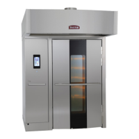
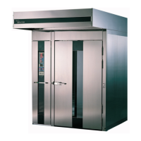
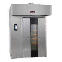
INSTALLATION INSTRUCTIONS OV500-EE SERIES GAS RACK OVENS AND OV500 SERIES ELECTRIC RACK
OVENS - INSTALLING OVEN
Page 45 of 49 F45469 Rev. D (1019)