B. Turn gas supply ON to oven and check for
leaks between gas valve and supply line
shut-off valve.
C. Verify that the static line pressure to the
oven does not exceed 14" W.C. (1/2 psig,
35.6 cm W.C., 3.5 kPa)
NOTE:
If static line pressure exceeds 14" W.C. (1/2
psig, 35.6 cm W.C., 3.5 kPa) the customer must
supply and install a line pressure regulator to drop the
pressure below 14" W.C., 35.6 cm W.C., 3.5 kPa
D. Turn gas valve ON.
E. Set the oven to call for heat.
NOTE: It may take several ignition attempts to light
burner initial time.
F. With oven burner flame established and with
the burners lit for all other equipment that
are common to supply line, check
SUPPLY
FLOW PRESSURE CHARTS.
G. With a burner flame established, adjust
manifold pressure as indicated on the oven
data plate
.
NOTE: The
ALTITUDE CORRECTION CHARTS are
for reference only. If the manifold pressure must be
adjusted to
accommodate the installation altitude you
must contact Bakery Product Support for a corrected
data plate.
12. Initial heating of oven.
A. Press the VENT key to open baking
chamber vent.
B. Leave loading door ajar approximately 2" to
evacuate smoke and prevent tarnishing of
oven interior, but not open far enough to
prevent operation of oven.
C. Set the oven control baking temperature to
300°F (150°C.). and bake timer for 30
minutes.
D. After time elapses, press STOP key to
silence beeper.
E. Fully open loading door to verify that baking
compartment circulation blower de-
energizes.
F. Set the oven control baking temperature to
400°F (200°C.). and bake timer for 30
minutes. Leave loading door ajar
approximately 2".
G. After time elapses, silence the beeper and
allow oven to heat for an additional 30
minutes with loading door closed.
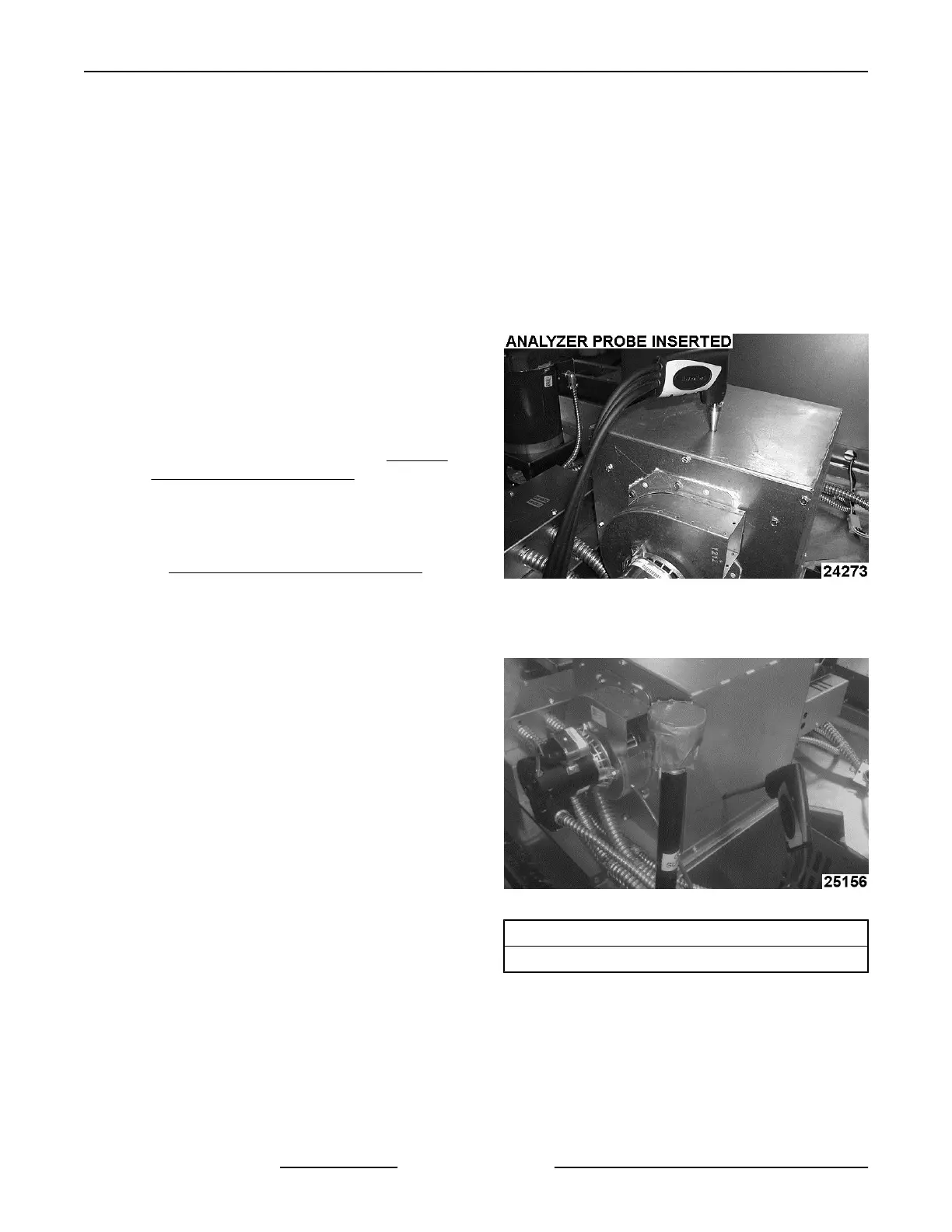
13. Combustion analysis.
A. Allow oven to cool to 300°F (150°C.).
B. Set oven temperature to 450°F (230°C.) and
with burner flame established, insert
combustion analyzer meter into air sampling
hole and take combustion measurements
O2 and CO air free readings.
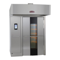
NOTE: Location of the air sampling hole will be either
on top of, or on the side of the draft inducer assembly.
Refer to pictures below for location of air sampling
hole.
Fig. 127
NOTE: If air sampling hole is on the side, insert the
probe at a 45° angle.
Fig. 128
O2: ( Range 6% to 8%)
CO Air Free: Not to exceed 0.04% (400PPM)
1) If reading can not be obtained, adjust
the draft inducer baffle and retest for
combustion.
INSTALLATION INSTRUCTIONS OV500-EE SERIES GAS RACK OVENS AND OV500 SERIES ELECTRIC RACK
OVENS - INSTALLING OVEN
F45469 Rev. D (1019) Page 46 of 49