BA series pumps
Pump unit with electric drive 1401
7.3
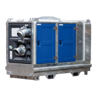
The actual control panel may therefore differ from the illustration.
1. Malfunction indicator light
2. Control panel lock
3. Hour counter
4. Selection switch
5. Float switch connection ‘low liquid level’
6. Float switch connection ‘high liquid level’
– Malfunction indicator light (1) lights up in the event of a pump unit
malfunction. This could result from activation of a protection circuit, for
example.
– The control panel can be opened via the lock (2).
The electrical panel is located behind the control panel.
WARNING
Always switch off the voltage before the control panel is opened.
– The hour counter (3) indicates how long the pump has been in operation. This hour reading is also
important for determining when the pump unit requires maintenance.
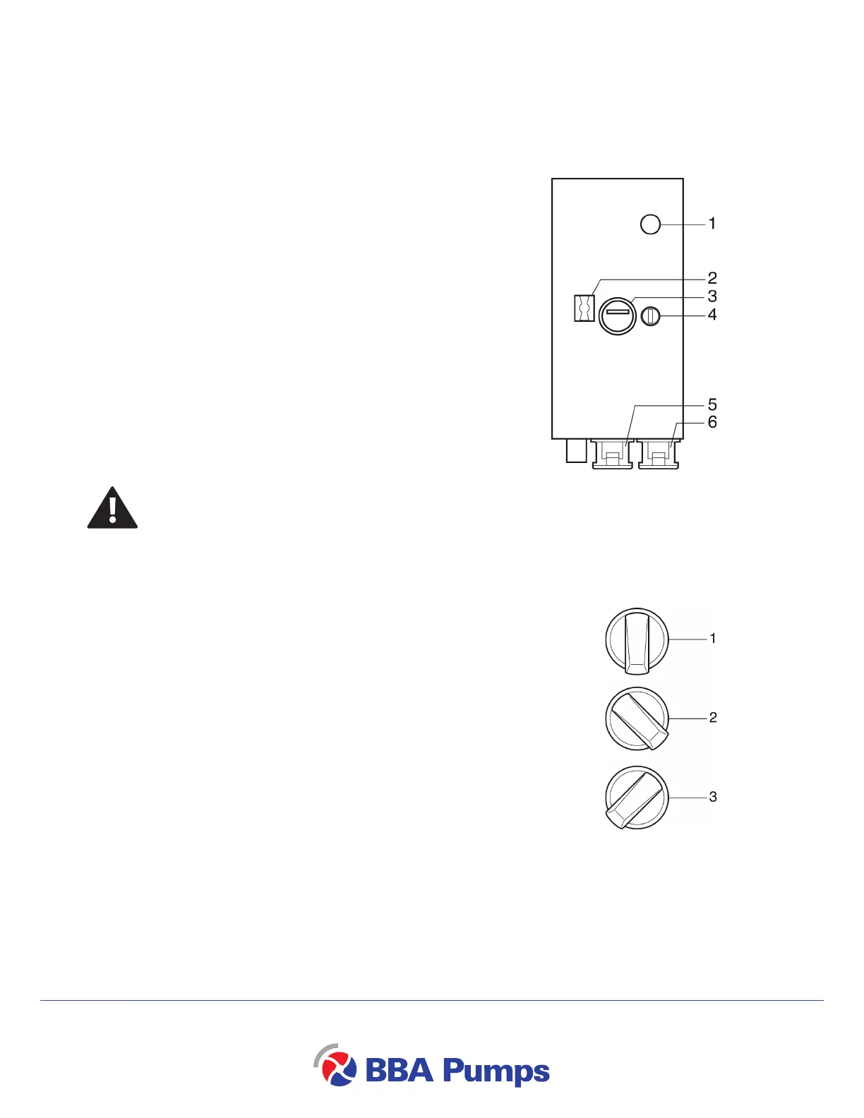
– Switch (4) has three functions:
– (1) Pump unit is switched off.
(2) Pump unit is switched on manually and runs continuously.
Note
To prevent damage to the pump it is important that the pump can draw
sufficient liquid.
– (3) The pump unit is set to ‘auto start’.
This means that the pump unit will switch itself on at certain times.
The activation parameters can be set by the user by means of the two float
switches.
If the pump is running in ‘auto start’ mode, the float switches must be
connected to the control panel.
Because the system is designed for delayed start-up it may take some time
before the pump unit begins to run.
– Connections (5) and (6) are intended for connection of the float switches for determining the liquid
level.
It is also possible to connect a pressure sensor to these connections (available as an option).
 Loading...