BA series pumps
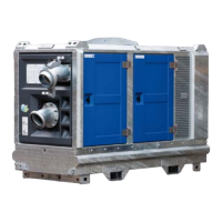
Pump unit with diesel drive 1401
8.4
WARNING
When float switches are used the pump unit may start automatically. Therefore
always switch off the power when working on the pump unit.
8.4 Control panel for electronically regulated engine
Note
The LC30 can optionally be used for a mechanically regulated engine. In that case, a number of
functions on the control panel are unused.
The pump unit is equipped with an LC30 control panel.
1. LCD screen
2. Auto standby LED (green)
3. Glow plug LED (yellow)
4. Stop LED (red)
5. Warning LED (yellow)
6. Button for changing engine speed
7. Selection switch
8. Float switch connection ‘low liquid level’
9. Float switch connection ‘high liquid level’
– If the Auto standby LED (green) is on, the key switch is in
the auto-start position and the system can be started.
– If the glow plug LED (yellow) is on, the system is being
preheated. When the LED goes out the engine can be
started.
– If the stop LED (yellow) is on, the ECU has stopped the
engine due to a fault.
– If the warning LED (yellow) is on, the ECU has issued a
warning.
WARNING
Maintenance on the electrical system may only be performed after the power supply
has been disconnected.
These activities may only be performed by personnel with the appropriate training
and authorisation.
 Loading...