# Auto mode selection
# Compatible with CS5341 pin
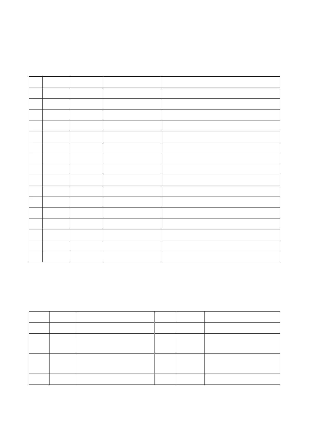
3.Pin function of CS5340 is shown as the following table:
Pin
Name Data direction
Function Remark
1 M0 I Mode selection Decide the operation mode of element
2 MCLK I Main clock
Δ-δclock source of adjustor and digital filter
3 VL I Logic power supply Forward power supply of digital input/output
4 SDOUT O Series audio data output Two's complement of output series audio data
5 GND Analog
6 VD I Digital power supply Provide forward power supply for digital part
7 SCLK I/O Series clock Provide series clock for series audio interface
8 LRCK I/O Left/right clocl Left/right audio time sequence control clock
9 RST I Reset Element enters a low-consumption state when in low level
10
AINL I Analog input
11
VQ O Static voltage
12
AINR I Analog input
13
VA I Analog power supply Provide forward power supply for analog part
14
REF_GND
Reference Provide reference ground for internal sampling circuit
15
FILT+ I Forward reference voltage
16
M1 I Mode selection Decide the operation mode of element
3.5.10 Function introduction to 4558/4580
4558/4580 includes two integrated operational amplifiers inside, with pin function shown as follows:
Pin Data direction
Function Pin Data direction
Function
1 O Output of operational amplifier A 5 O Output of operational amplifier B
2 I
Negative input terminal of operational
amplifier A
6 I
Negative input terminal of operational
amplifier B
3 I
Positive input terminal of operational
amplifier A
7 I
Positive input terminal of operational
amplifier B
4 I (minus) 12V voltage input 8 I 12V voltage input
- 85 -