TX1500 Manual V3.5 Dec 07 Page 33 of 40 TX1500/BBUS-I/F INTERFACE
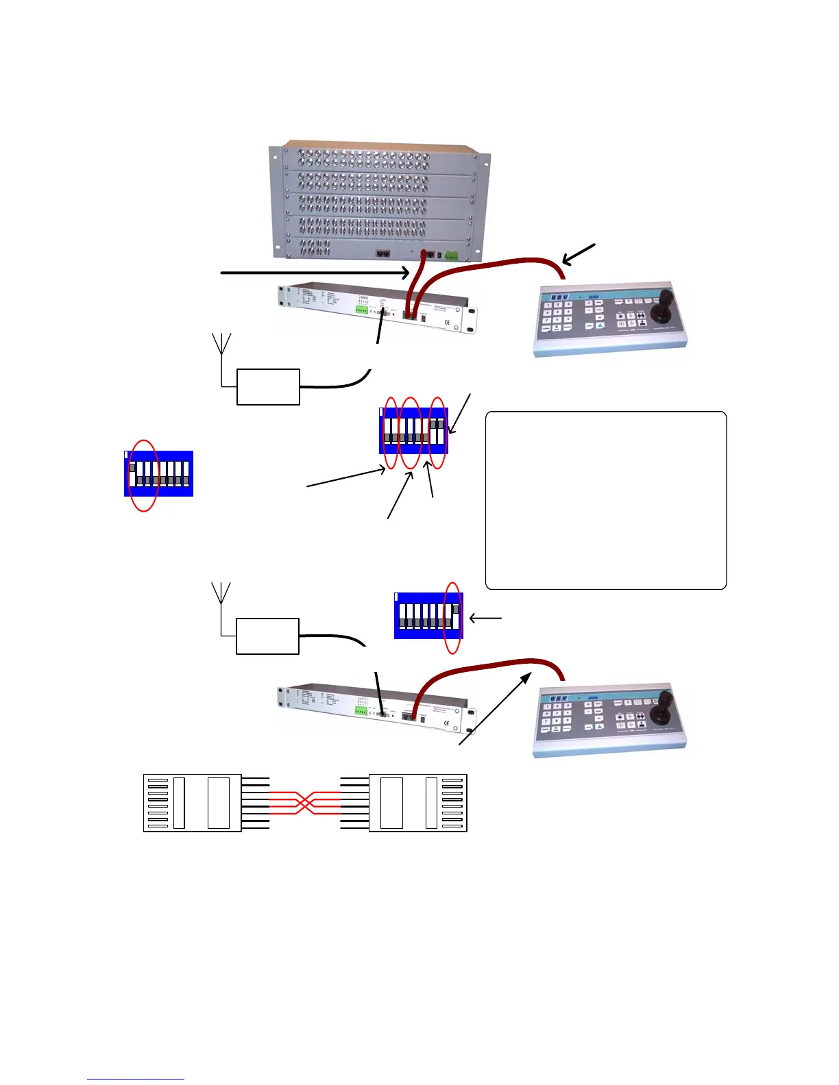
RF Link
TX1500 KEYBOARD
(Addressed as 0)
(SW1-5 OFF)
BBUS I/F
RJ45 Cable with 3 & 4 swapped and 5 & 6 swapped
12 3456 78
ON
1-7 OFF, 8 ON at KEYBOARD END
RS232-9600,N,8,1
RF Link
TX1500 KEYBOARD
TX1500 MATRIX
BBUS I/F
Standard RJ45
CAT5 patch cable
RS232-9600,N,8,1
Standard RJ45
CAT5 patch cable
SW4 Setting
12 3456 78
ON
7 & 8 ON at MATRIX END
1 & 2 selects keyboard address
3,4 & 5 selects monitor
6 not important
BBUS I/F FOR REMOTE TX1500 KEYBOARD
12 3456 78
ON
ON - Remote keyboard mode
SW3/1-4 must be as shown at both ends.
SW3 setting
SW4 Setting
The BBUS Interface at the keyboard end of the link
sends a stop command if the joystick/lens is not
active every 5 seconds. This is used to help with
links that could lose data.
If the link is bi-directional, then the following led flash
sequence will be seen.
1. KEYBOARD END GREEN (data out)
2. MATRIX END YELLOW (data in)
3. MATRIX END GREEN (data out)
4. KEYBOARD END YELLOW (data in)
If the link is a simplex link then just steps 1,2 and 3
will be seen as the data will get back into the
KEYBOARD end interface.
1
8
8
1
3 - 4
4 - 3
5 - 6
6 - 5