TX1500 Manual V3.5 Dec 07 Page 34 of 40 TX1500/BBUS-I/F INTERFACE
02005 Iss 2
LD1
B-BUS
SW4
SW1
SW3
LD2
LD3
POWER
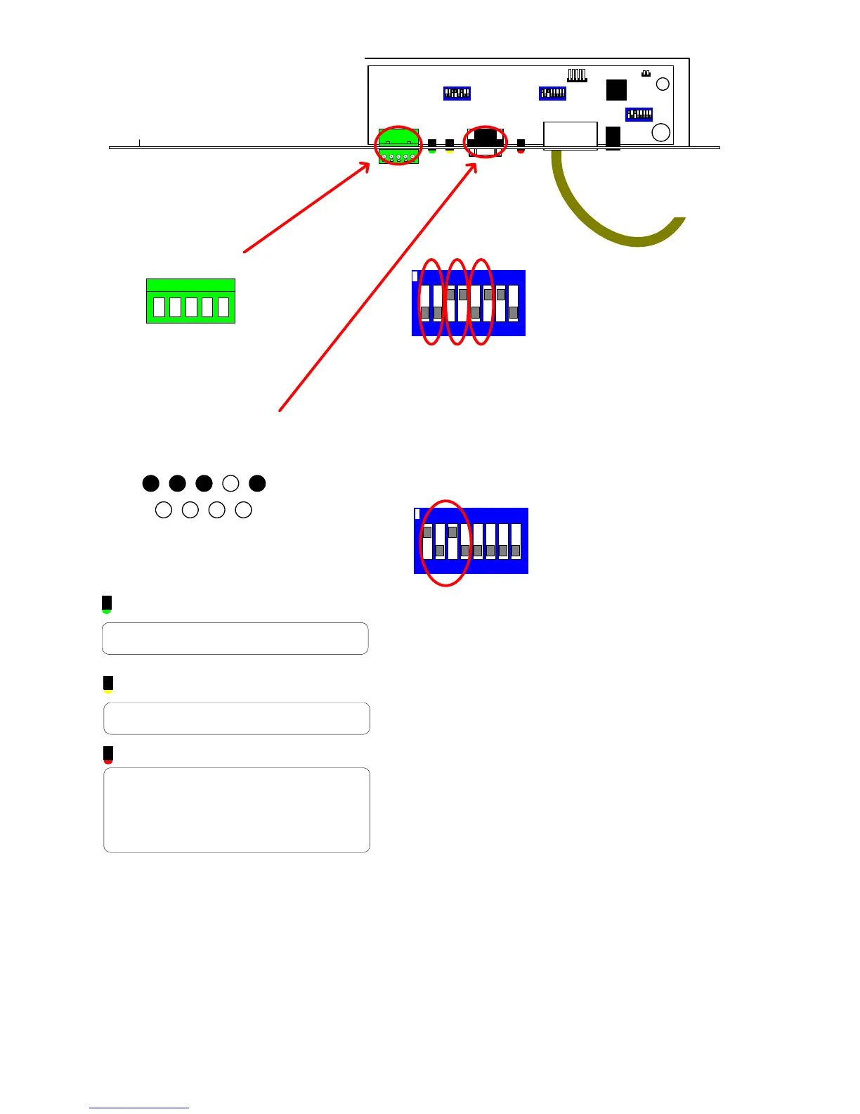
Chassis Mount DB9 Male
1 2 3 4 5
7 8 96
+V OUT
RS232 IN
RS232 OUT
GND
RS232
RJ45 to FBMCPU BBUS
5 RB/-(IN)
RS485/422
4 RA/+(IN)
3 TA/+(OUT)
2 TB/-(OUT)
1 GND
TX1500 BBUS Interface
FBMCPU MODE-8 KEYBOARDS
LED guide
GREEN LD1
Flashes when the interface sends an LED
status to the RS232 port.
YELLOW LD2
Flashes when interface receives a command
from the RS232 port.
RED LD3
BBUS comms status.
OFF = Unit de-powered
ON = Unit Powered but not communicating
with the FBMCPU.
Pulsing Very Fast = Comnunicating correctly.
1/2 = BBUS termination
Must be ON only when the interface is at the
end of line.
Default = OFF
3/4 = RS485 termination
Must be ON only when the interface is at the
end of line. Default = ON.
5/6 = RS232 or RS485 selection.
SW1/5 SW1/6 Input
ON OFF RS485
OFF ON RS232
ON ON DO NOT USE
7 = MUST BE ON
8 = NOT USED
7812 3 546
ON
SW1 Settings
7812 3 546
ON
SW3 Select mode
1-4 set the switches as shown to select FBMCPU
mode which allows 8 keyboard addresses
SW3 - Mode
This mode is to allow the BBUS/I-F to connect to the processor of our larger FBM matrix system. The FBM matrix
allows up to 8 keyboard positions where the standard TX1500 mode allows 4 addresses.
If the BBUS/I-F is used with a TX1500 then DO NOT use this mode.