22
ENG
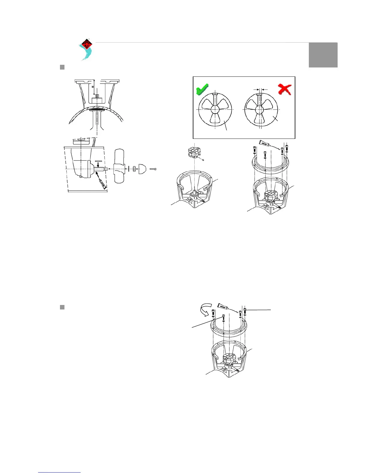
2.5 ASSEMBLING OF THE PROPELLER AND THE OIL RESERVOIR
Check again dimension `H`. (Fig. 26).
Make sure that the key is properly positioned in the key way of
the shaft. Grease the shaft with outboard gear grease and
install the propeller with the lock washer and the hexagonal
nut. Secure the nut by bending the tag of the washer. Fit the
zinc anode to the propeller shaft by means of the bolt. (Fig. 27)
The propeller should run a minimum of 1,5 mm free of the
thrust tube wall, all round (Fig. 28).
Grease the input shaft with an installation compound, like
Molykote ® G-n plus. Fit the flexible coupling to the input shaft
of the tail piece and sec ure the coupling with the locking screw.
Grease the shaft of the electric motor with an installation
compound, like Molykote ® G-n plus. Grease the threads of
the fastenings bolts with ‘outboard gear grease’ and install the
electric motor to the intermediate flange. Use one of these
bolts to fasten the relay support as well. For a first check, turn
the propeller by hand, it should turn easily, whilst being
connected to the output shaft of the electric motor (Fig. 29).
Assemble the oil reservoir over the water line level at a
height minimum of 500mm/ 20in. So that to ensure that there is
sufficient over pressure of oil in the tail piece. (Fig. 30). Ensure
that the tube does not form any air traps, which will restrict the
oil, to flow freely and that it has a correct angle that the oil
flows freely to the tail piece. Fill the reservoir with gear oil type
EP90.
2.6 ASSEMBLING THE ELECTRIC MOTOR
Rotate the pilot shaft of the tail piece and rotate the shaft of the
motor in a way that the seating of the safety shear pin is in line
with that of the security pin on the shaft of the electric motor.
Slide slowly the electric motor on the pilot shaft and the motor
flange. It could be necessary to move it on either side to
inserted in, as could be slightly hard.
The electric motor could be positioned in any direction on the
flange. Verify that the cable terminals are available for the
following electrical installation.
Tight the screws for holding the electric motor (supplied) with a
torque of 17Nm /12.4lbft (Fig. 31).
As a first check, rot ate the propeller by hand, which has to
rotate freely, even though it is connected to the motor shaft.
Fig. 28
Tunnel
Distance
propeller/tunnel
Tunnel
Fig. 26
Fig. 27
Fig. 29
Fig. 30
Screws 17Nm/12.4lbft