25 BOW THRUSTER BT160Kgf
ENG
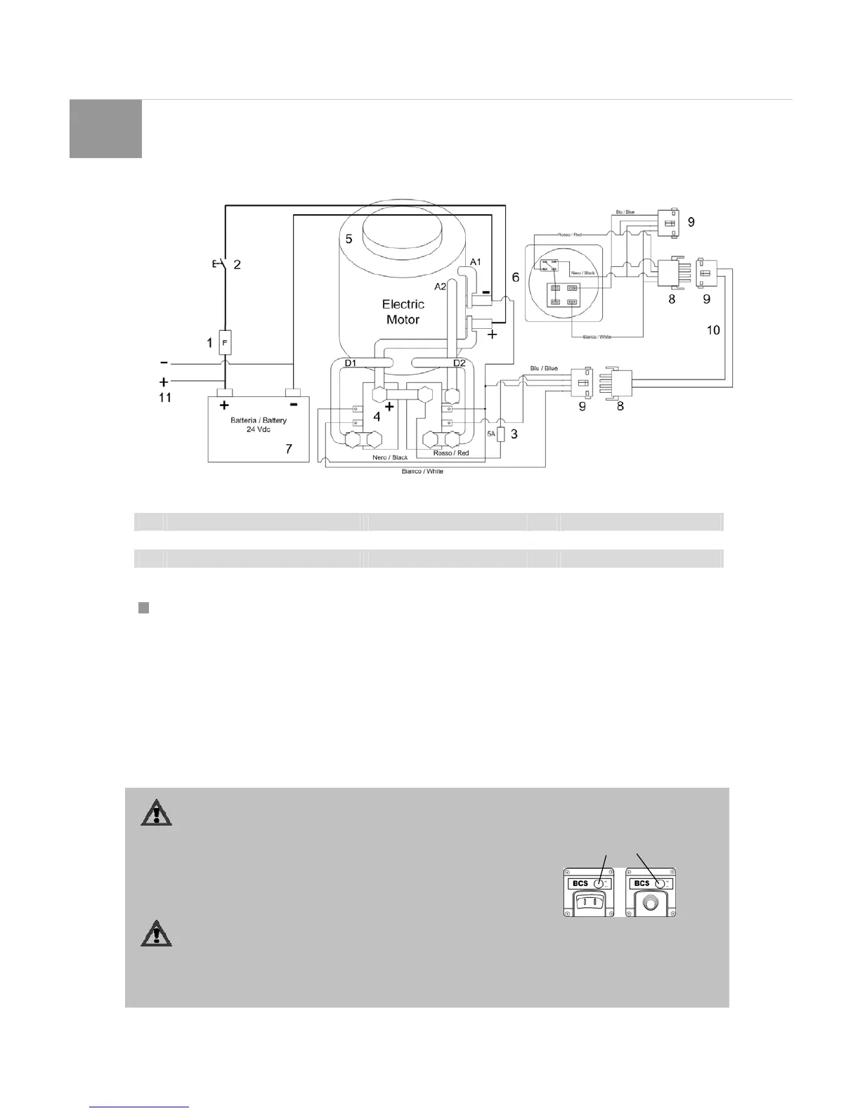
ELECTRIC DRAWING
1 Main Fuse 5 Electric Motor 9 Female Plug
2 Main Switch 6 Control Panel 10 Coupling cable
3 Fuse Control circuit 7 Battery 11 Alternator
4 Relay Switch 8 Male plug
4 FUNCTION
According to the lateral area exposed to the wind, the fly
bridge and the shape of the boat, the thrust generated by the
bow thruster will result differently from one boat to another.
The nominal thrust is achieved only in optimal conditions.
Ensuring that the operation the battery voltage is correct.
The installation must be performed in respect to the
recommendations indicated in the installation instructions, with
particular reference to:
•
Limit voltage drop along the battery cables ut ilizing
sufficient diameter.
• The way the tunnel is connected to the hull.
•
Install the bars in the tunnel opening only if strictly
necessary.
Respecting the following recommendations the bow thruster
will last longer and obtain better performance:
• Perform regularly the maintenance operations.
•
Do not rotate the propeller for long; for thermal protection
reasons, the maximum duration is limited. After some time
of operation, the motor must be left to cool down.
The maximum duration of operation, that is als o the maximum
hour duration of operation, is for BT160Kgf-24Vdc 3min a
500A.
ATTENTION!
During operation of the bow thruster pay attention to swimmers or small boats that might be close to the opening of
the tunnel.
If two control panels are installed, do not operate simultaneously the two
joysticks.
• Switch on the main switch (Fig. 35).
•
Push switch “ON/OFF”. The lamp will light and the propeller is ready for us e.
•
The motor will be activated through the switch selected.
ATTENTION!
Do not pass in one moment from port to star port or vice versa, but give time to the motor to stop rotating
completely, before start rotating in the opp osite direction.
• After the bow thruster is used turn the switch “ON/OFF” again.
•
Before going down the boat, turn the main switch off.
Main Switches
Fig. 35