24
ENG
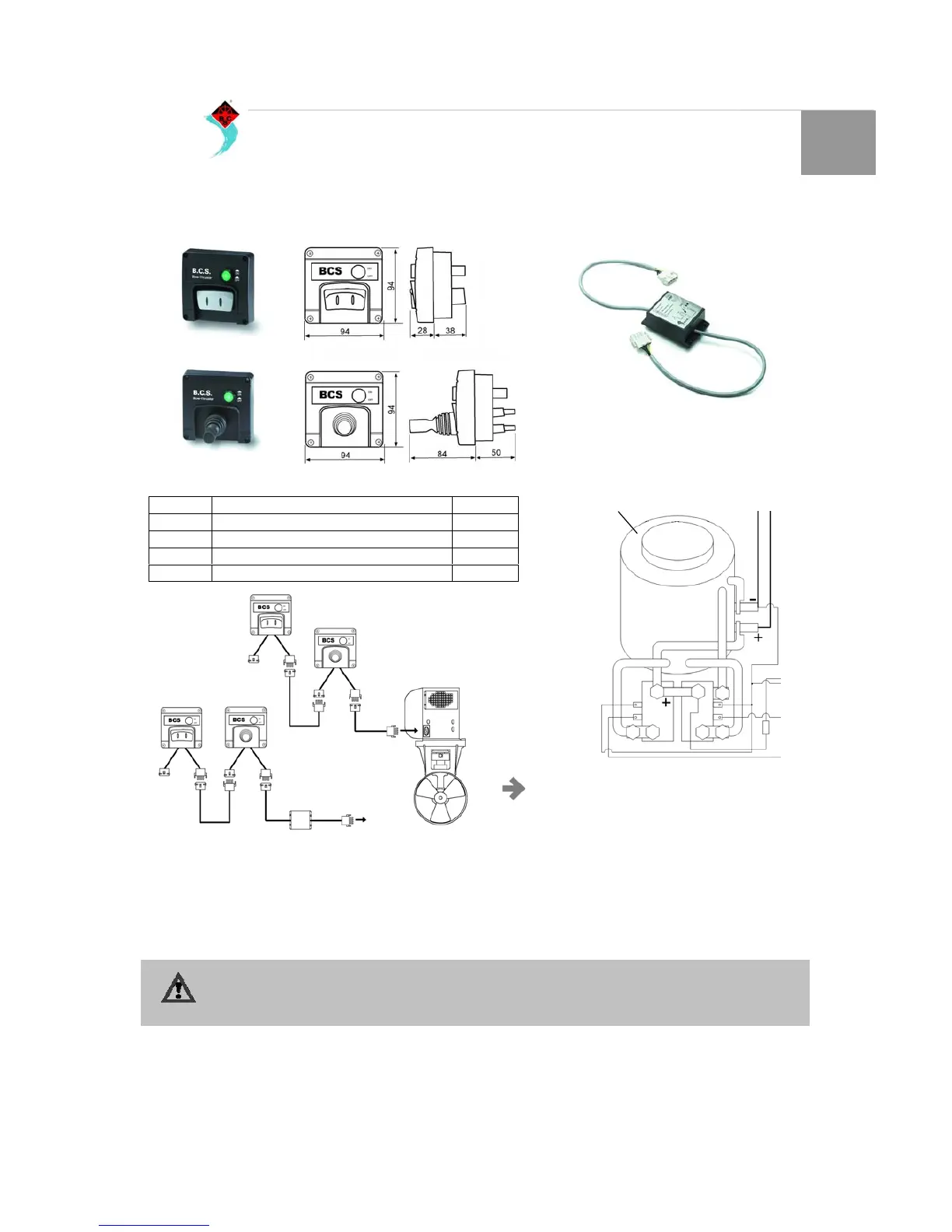
CONTROL PANEL AND ACCESSORIES
Install the control panel on the dashboard. A free space of at
lease 50 mm must be left free behind the panel. (Fig. 33).
Install the coupling cable between the bow thruster unit and
the control panel from the internal of the boat and connect the
plugs. If necessary cut the cable and re-connect ensuring that
the cables are placed according to colours.
N.B. The cable colours could be different from the
coupling cable utilized on the motor or on the
control panel!
Its possible to install a delay switch between the bow thruster
and the control panel (BTRIT), which will give the time
necessary to the electric motor to stop from rotating, when in a
single moment switching from port to starboard and port again.
If there are two stations, the second can be connected to the
first.
If it happens t hat during testing the direction of thrust does not
correspond with the direction of the switch on the control
panel, the blue cable (A) and the white cable (B) on the relay
must be inverted (Fig. 34).
ATTENTION!
Do not test the Bow-Thruster when the boat is out of water, or at least you are sure that no one is close to the
tunnel. When the boat is out of water do not operate the motor for more that 5 seconds.
MODEL DESCRIPTION CODE
BTJOY Bow thruster Control panel with Joy Stick 15726
BTINT Bow thruster control panel with switch 15727
BTRIT/12 Delay switch kit 12V 12214
BTRIT/24 Delay switch kit 24 v 12215
CONTROL PANEL
Fig. 33
BTINT
BTJOY
BTINT
BTJOY
BTRIT
DELAY SWITCH
Fig. 34
Electric Motor
White cable
Blue
cable