23 BOW THRUSTER BT160Kgf
ENG
3 ELECTRICAL INSTALLATION
ATTENTION!
The maximum duration of operation and the
thrust indicated in the technical data are based
on the relative recommendations of the battery
capacity and the length of cables.
The use of higher capacity batteries in
combination with short cables and large cross
section cables than recommended, will increase
the thrust. In such case reduce the maximum
operating time, to prevent from damaging the
motor.
In extreme case, for example, when batteries with 5
volts capacity or more than that suggested are
utilized, there is the danger that the security shear
pin breaks more frequently
Also there is the danger that one or both shafts coupling
get damaged permanently:
• The coupling between the electric motor shaft
and the pilot shaft on the tail piece
• The coupling between the propeller shaft and
the propeller.
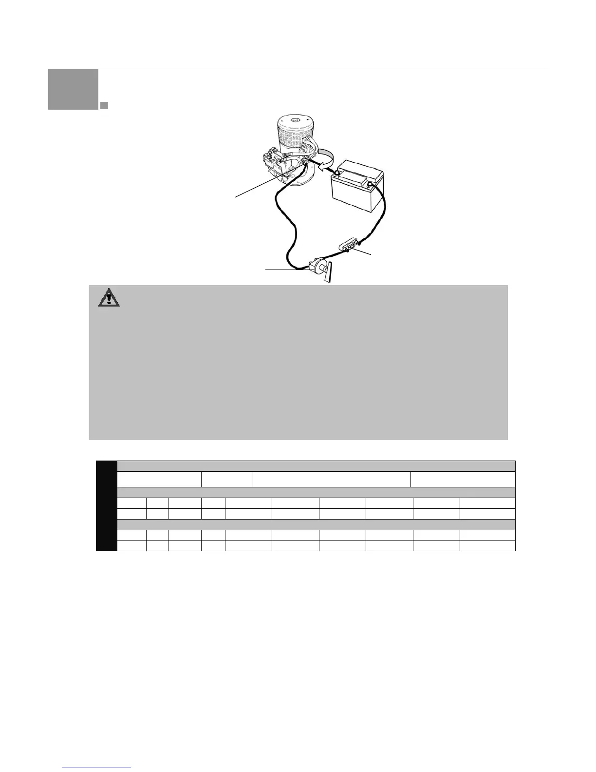
Check that the voltage indicated on the motor tag corresponds
with the voltage of onboard. Position the batteries or place
them as close as possible to the bow thruster. The supply
cable can therefore be short, reducing to a minimum the
voltage drop.
Its important to utilise adequately sized cables and batteries
with elevated capacity at cold for the supply of the unit
because is the effective voltage in correspondence with the
motor when the unit is operated which determines the revs of
the motor and so the thrust.
The following list indicates recommended dimensions for cables and batteries (Tab. 1):
Amainswitch(A) capable to take the load without losses has
to be connected in line to the main positive supply, in a way
that the unit could be isolated independently from ot her
equipment on board when no one is on board or in case of
emergency. This has to be installed in an easily accessible
place and on the instructions of the boat has to be noted that
this has to be turned off as well as other main s witch on board.
(Fig. 32).
We recommend also installing a fuse (B) on the positive as a
protection against short circuit of the main cables. Such fuse
must be of premium quality that is its standard explains t he
physical quality dimensions, which fuse offer low voltage
resistance with respect to other simple smaller fuses. The fuse
must be of a slow blow type and dimensioned in such a way
that it can resist the nominal current for at least 5 minutes.
The fuse must be of a slow blow type and dimensioned in
such a way that it can resist the nominal current for at
least 5 minutes.
The end of the c ables must be terminated with terminals and
these must be well insulated, excluding any contact with any
other contact point that can be connected.
Tight the M8 screws with a torque of 15Nm/11lbft (Fig. 32).
Minimum Dimensions for cables and batteries.
Current absorbed
500 A 24Vdc
Minimum battery capacity recommended (cold
starting capacity according to DIN STANDARDS)
600 CCA DIN (24 Vdc)
Maximum cable length from batteries to the bow thruster and return in meter [m] given the cable section (mm
2
)
mm
2
25 35 50 70 95 120 150 175
24 Vdc m N/R 6 10 20 25 35 45 N/R
Maximum cable length from batteries to the bow thruster and return in feet [ft] given the cable section (AWG)
AWG
3 2 1 0 00 000 0000 2x0000
BT160
24 Vdc ft N/R 25 30 50 65 80 95 N/R
Main switch (A)
Fuse (B)
Battery
Fig. 31
Screws
15Nm/11lbft