19 BOW THRUSTER BT160Kgf
ENG
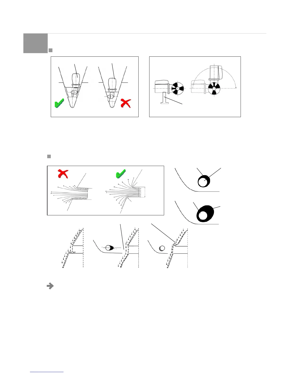
2.2 LOCATING THE BOW THRUSTER IN THE TUNNEL
At the moment of locating the position of the propeller i n the
tunnel is necessary to keep present that the tail piece should
NOT protrude out of the tunnel. The bow thruster should
preferably be located at the centre of the boat and also
reachable from the external. (Fig. 8).
The motor could be mounted in various positions. If the motor
is located horizontally, or at a degree larger than 30°respect to
the vertic al, is absolutely necessary to support the motor. The
motor should always be located above the highest level of the
drainage water. (Fig. 9).
2.3 ASSEMBLING THE TUNNEL IN THE HULL
NB: The way the tunnel is located in the hull
influence enormously the thrust of the propeller and
the drag of the hull during normal sailing.
We recommend rounding as possible the connections between
the tunnel and the hull. The optimal radius is that of 10% the
diameter of the tunnel. The advantages over a connection with
sharp edges are:
• A tunnel with extreme radius prevents the creation of
turbulence and cavitations avoiding losses of thrust and
noise (Fig. 10 e 11).
•
A tunnel with extreme curve helps the bow thruster to pull
more water along the hull sides , creating a suction that pulls
the boat laterally, resulting in an added thrust (Fig. 12 e 13).
• To avoid any loss of performance, the tunnel inlet can be
modified to increas e the thrust and reduce noise (Fig. 14). The
best solution that normally reduce resistance and realise a
reassess in the hull behind the tunnel. Basically one would not
see the back part of the tunnel when looking from the front of
the boat. The angle of the insert on the hull depends on the
shape of the hull, but is normally inclined slightly toward the
bottom because of the water flow in this location of the hull. The
resistance can be highly reduced, especially in fast boats,
creating a deflector / spoiler on the front of the tunnel. The
shape and the dimension of this deflector depend on the shape
of the hull.
Bow-thruster
Support
Bow-thruster
Fig. 8 Fig. 9
Extreem Sharpness
Diameter
tunnel
Extreem radius
Rmin=0.1xD
Tunnel
Tunnel
Extreem curve
Hull without
Reases
Reases in Hull
Fig. 11Fig. 10
Fig. 14
Fig. 12
Fig. 13
Extreem curve