Chapter 7: Technical overview 109
Compensation
theory
Fluorochromes emit light over a range of wavelengths. Optical
filters are used to limit the range of frequencies measured by a
given detector. However, when two or more fluorochromes are
used, the overlap in wavelength ranges often makes it impossible
for optical filters to isolate light from a given fluorochrome. As a
result, light emitted from one fluorochrome appears in a detector
intended for another. This is referred to as spillover. Spillover can
be corrected mathematically by using a method called
compensation.
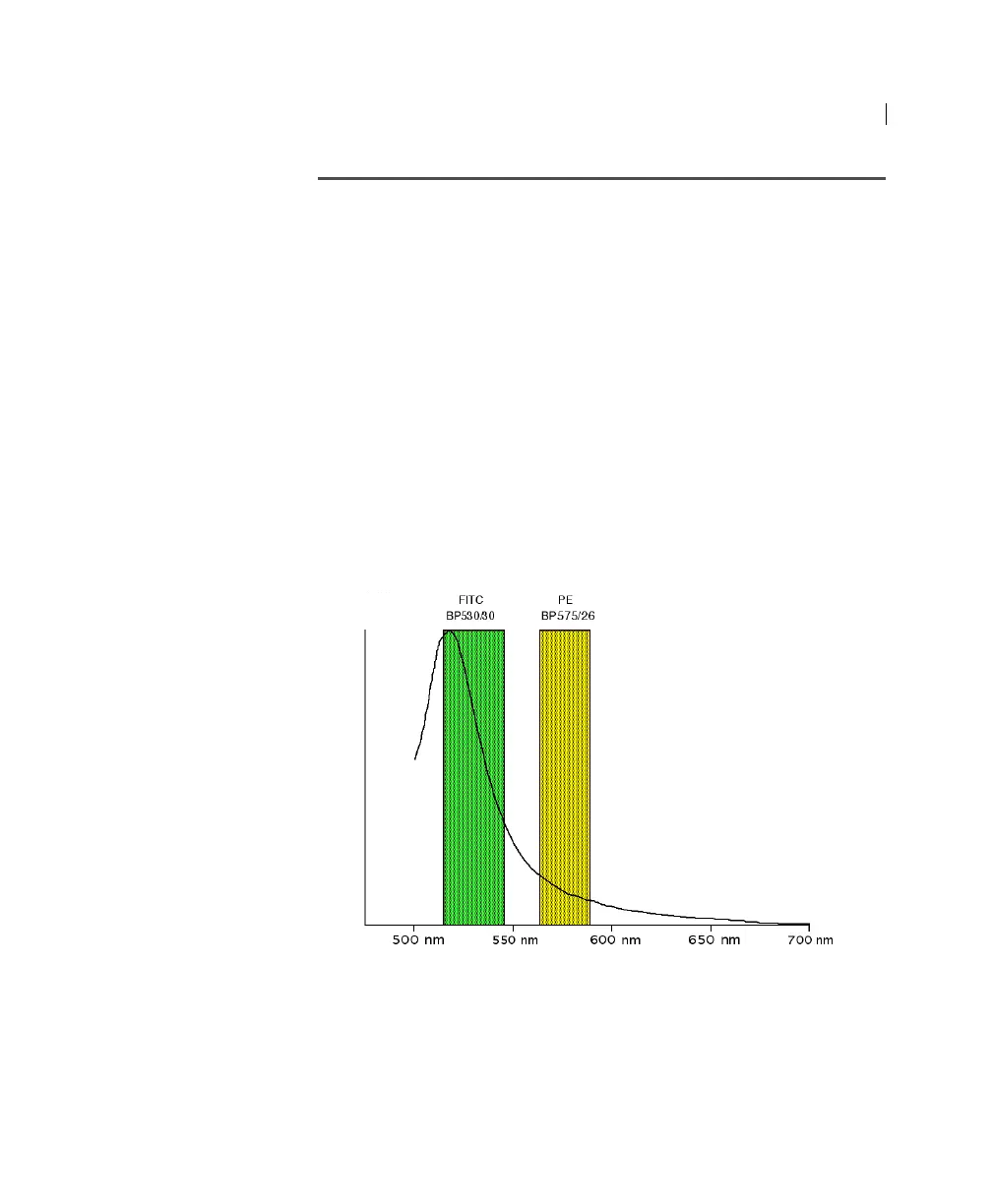
In the following example, FITC emission appears primarily in the
FITC detector, but some of its fluorescence spills over into the PE
detector. The spillover must be corrected or compensated for.
Alternatively, the spillover can be minimized by discrete excitation
of fluorochromes. In the following example, excitation with a
yellow-green configuration will help minimize spillover.
This spillover can be seen in a dot plot of FITC vs PE. The FITC
spillover in the PE detector must be corrected as demonstrated in
the two figures that follow.
Wavelength (nm)
Normalized intensity