75.5695.08 IS40 IS40XL 20230627 Page 5 of 8
0 – 9
1 – 6
IS40
IS40 XL
4
8
12
f
16
20
f
6
3 0
3
6
11.5 ft
16 ft
8 ft
4
8
12
f
16
20
f
6
3 0
3
6
16 ft
8 ft
11.5 ft
4
8
12
f
16
20
f
6
3 0
3
6
8 ft
11.5 ft
16 ft
4
8
12
f
16
20
f
6
3 0
3
6
10 ft
11.5 ft
8 ft
4
8
12
f
16
20
f
6
3 0
3
6
10 ft
11.5 ft
8 ft
4
8
12
f
16
20
f
6
3 0
3
6
10 ft
11.5 ft
8 ft
4
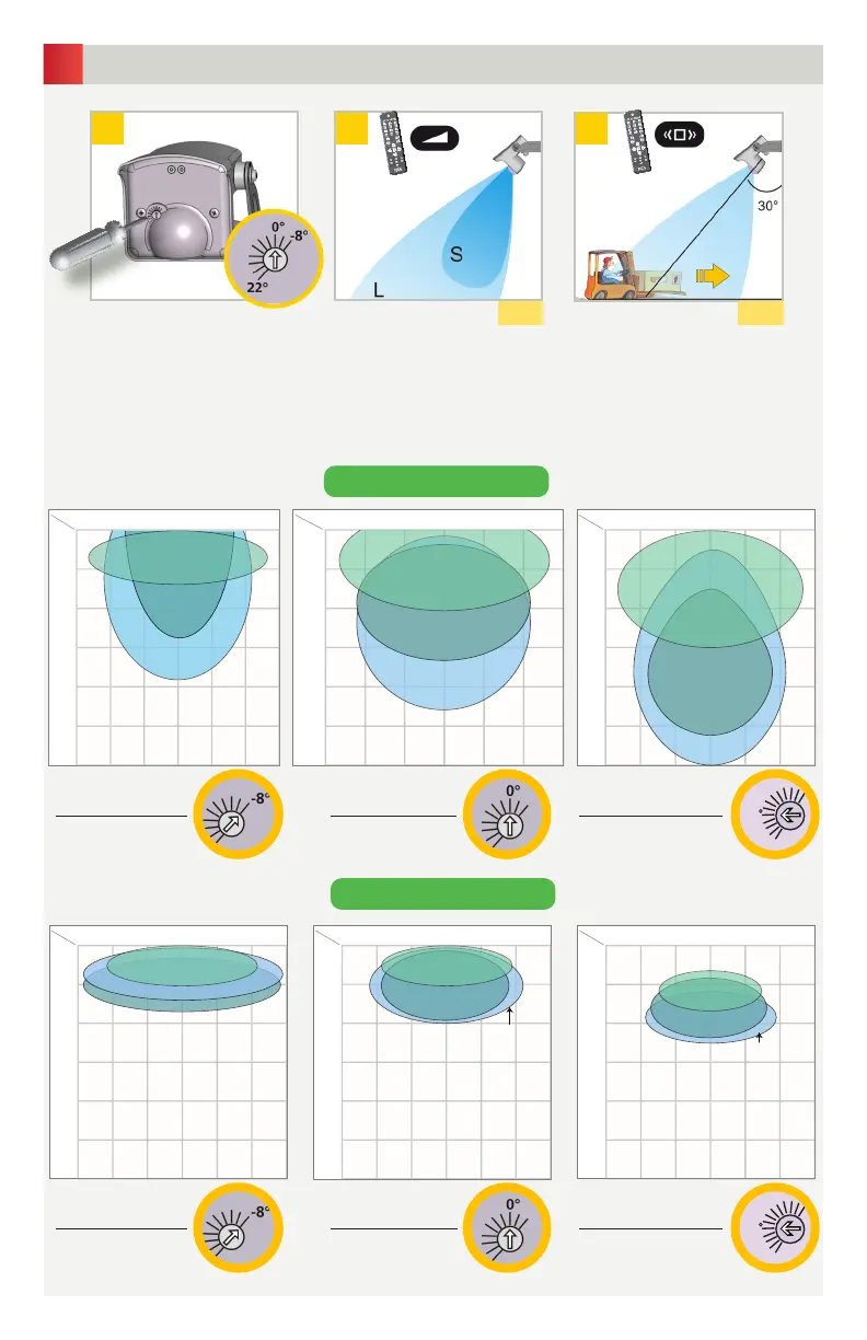
1 2 3
Adjust the field size.
S = 2, L = 7.
Choose the appropriate
detection filter for your application.
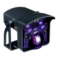
Turn this screw to adjust the radar
field angle from -8° to 22°.
p. 6 p. 6
The total angle is the sum of the sensor angle and the radar field angle.
SENSOR ANGLE + RADAR FIELD ANGLE = TOTAL ANGLE
All detection field dimensions were measured in optimal conditions with a sensitivity value of 7.
Sensor angle: 30°
Radar field angle: -8°
Total angle: 22°
Sensor angle: 30°
Radar field angle: 0°
Total angle: 30 °
Sensor angle: 30°
Radar field angle: +11°
Total angle: 41°
Sensor angle: 30°
Radar field angle: -8°
Total angle: 22°
Sensor angle: 30°
Radar field angle: 0°
Total angle: 30 °
Sensor angle: 30°
Radar field angle: +11°
Total angle: 41°
RADAR FIELD AND AIR PATTERN