List of figures
CP39xx52 Version: 3.6
List of figures
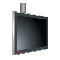
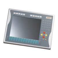
Fig. 1 CP39xx_without and with push button extension......................................................................... 9
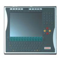
Fig. 2 CP39xx_Toolboard and handle.................................................................................................... 10
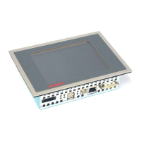
Fig. 3 CP39xx_Structure ........................................................................................................................ 11
Fig. 4 CP39xx-0000_connection block................................................................................................... 12
Fig. 5 CP39xx-0000_access to interfaces.............................................................................................. 12
Fig. 6 CP39xx-0000_voltage socket pin numbering............................................................................... 13
Fig. 7 CP39xx-0000_DVI-Extended input pin numbering ...................................................................... 14
Fig. 8 CP39xx-0000_USB-E input pin numbering.................................................................................. 15
Fig. 9 CP39xx-0010_connection block................................................................................................... 16
Fig. 10 CP39xx-0010_access to interfaces.............................................................................................. 16
Fig. 11 CP39xx-0010_voltage socket pin numbering............................................................................... 17
Fig. 12 CP39xx-0010_CP-Link 4 pin numbering...................................................................................... 17
Fig. 13 CP39xx-0010_CP-Link 4.............................................................................................................. 18
Fig. 14 CP39xx-0010_CP-Link 4, CU8802-00x0 ..................................................................................... 19
Fig. 15 CP39xx-0010_CP-Link 4, CU8803 .............................................................................................. 19
Fig. 16 CP39xx_optional USB interface................................................................................................... 21
Fig. 17 CP39xx_optional USB interface................................................................................................... 21
Fig. 18 CP39xx_name plate..................................................................................................................... 22
Fig. 19 CP39xx_Mounting arm adapter options....................................................................................... 29
Fig. 20 CP39xx_cable channel ................................................................................................................ 29
Fig. 21 CP39xx_opening the cable channel............................................................................................. 30
Fig. 22 CP39xx_opening the push button extension................................................................................ 30
Fig. 23 CP39xx_Adapter_plates .............................................................................................................. 31
Fig. 24 CP39xx_Installation mounting arm adapter ................................................................................. 31
Fig. 25 CP39xx_Mounting arm adapter installed ..................................................................................... 32
Fig. 26 CP39xx_Mounting arm tube installation....................................................................................... 33
Fig. 27 CP39xx_Protective conductor connection PE.............................................................................. 35
Fig. 28 CP39xx_Mounting arm adapter cable routing.............................................................................. 36
Fig. 29 CP39xx_cable routing procedure................................................................................................. 37
Fig. 30 CP39xx-0000_power supply cable strain relief plate ................................................................... 37
Fig. 31 CP39xx_M20 cable gland and 19-pin round connector with mounting arm adapter.................... 38
Fig. 32 CP39xx_M20 cable gland and 19-pin round connector with connection block ............................ 38
Fig. 33 CP39xx-0000_cable ties on strain relief plate.............................................................................. 41
Fig. 34 CP39xx_releasing the strain relief rail.......................................................................................... 42
Fig. 35 CP39xx_disassembly mounting arm tube.................................................................................... 43
Fig. 36 CP39xx_Toolboard and handle.................................................................................................... 43
Fig. 37 CP39xx_Select "Cleaning Mode"................................................................................................. 46
Fig. 38 CP39xx_Configuration "Cleaning Mode" ..................................................................................... 46
 Loading...