GB Sound speed controller SFR-1
06.02.2019 BEIER-Electronic 13
Connection of switching-outputs
The outputs 1 -16 of the module are located at the pin connectors X3 and X4.
The supplied ribbon cable can be used to connect the outputs. For easier
connection, the terminals AKL-8 and AKL-8-W can be ordered from our shop.
Of course other cables/plugs with a cross section of 0,14 mm² - 0,5 mm² can be
connected as well.
The SFR-1 is always switching the negative pole to each output and thus to the
connected load. The positive pole is always connected permanently to the load (see
wiring diagram).
The common positive pole for outputs 1 – 8 and 9 -16 are the clack and white
cables. It is also possible to connect the load directly to the positive pole of the
battery.
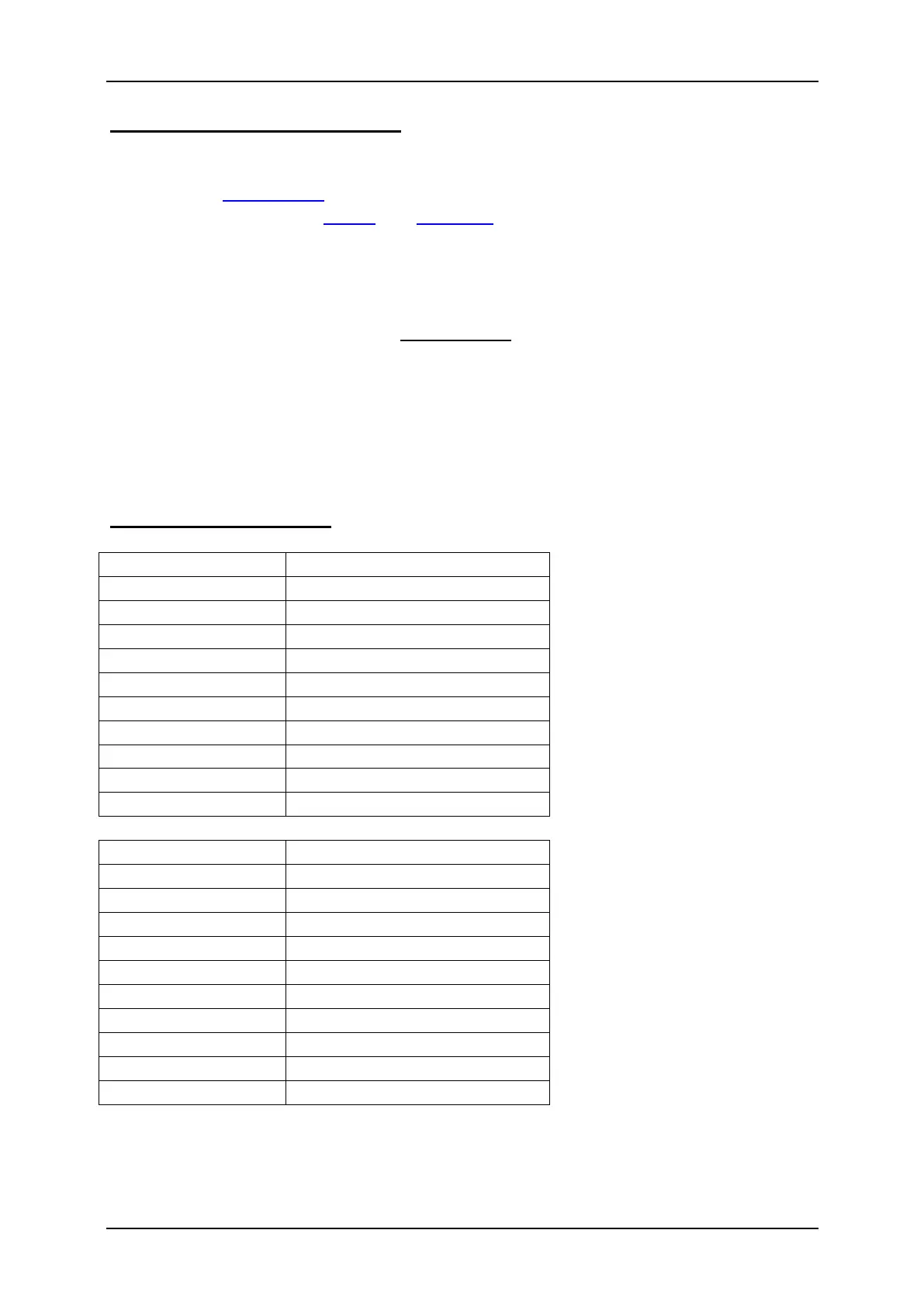
Ribon cable assignment:
The switched voltage at the outputs (with 100% intensity) is always as high, as the
supply voltage of the SFR-1. For example if the module is supplied with 12V, only
lamps with 12V should be connected.
 Loading...