GB Sound speed controller SFR-1
14 BEIER-Electronic 06.02.2019
If you want to connect LEDs, series resistors are always required. Furthermore,
attention must be paid to the correct polarity of the LED. The series resistors for the
LED’s are depended on the supply voltage, the LED-color and the LED-current.
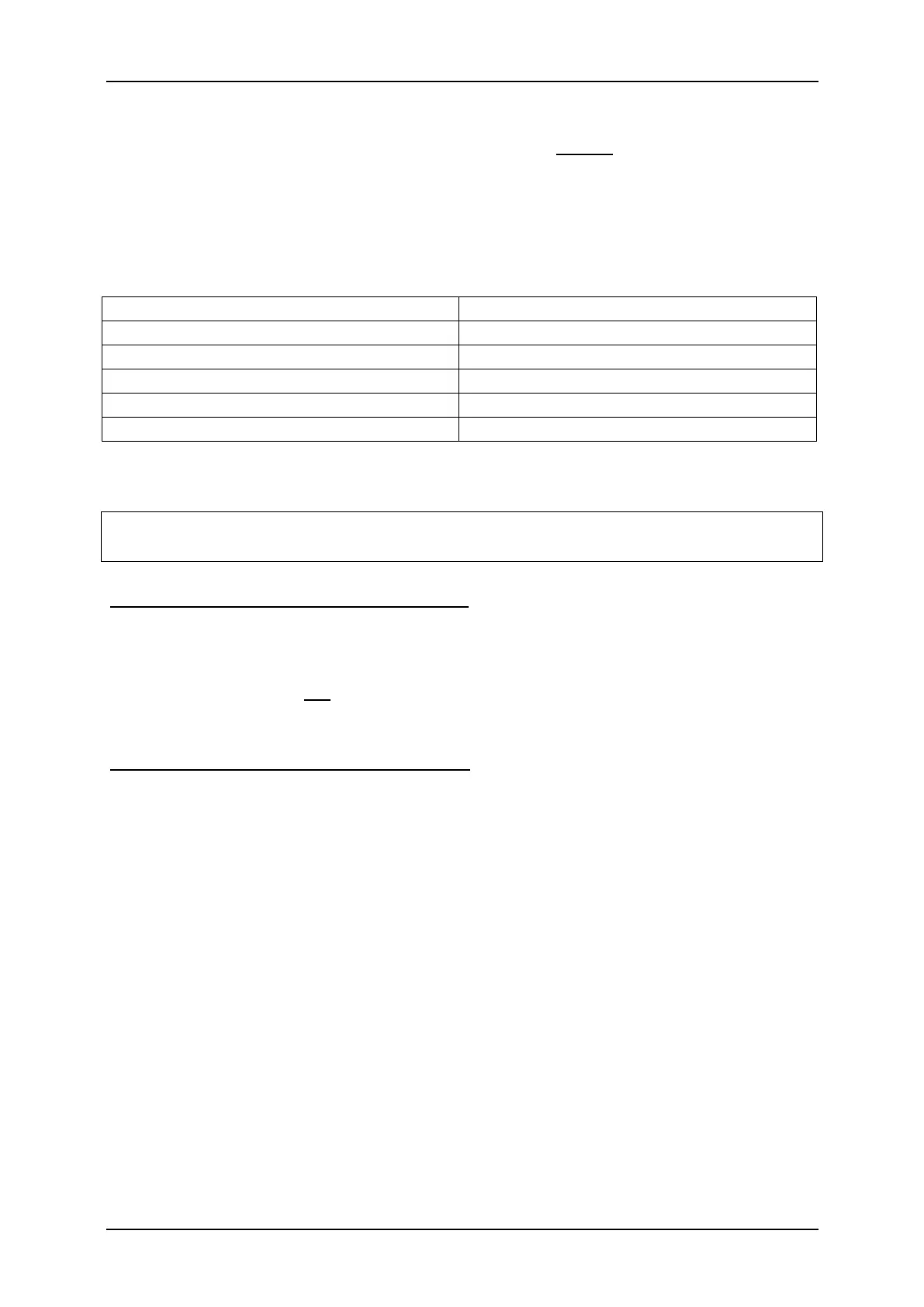
The table below shows the resistance values required for standard LEDs (approx. 15
mA current):
In the internet you will find various pages to calculate the necessay resitor value.
If multiple LEDs are connected to one output (e.g. front and rear direction indicators),
it is always better to use separate resistors than to connect the LEDs in series.
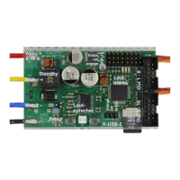
Connection of data cable K-USB-2 (X6/2)
The data cable K-USB-2 is connected to X11. The brown cable points to the SD
card.
The speed controller is not powered by the data cable. For using the data cable, the
SFR-1 must be supplied with power via the battery as normal.
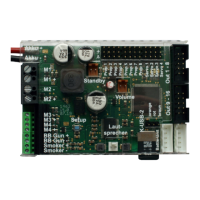
Connection of an optional "main switch"
An optional switch can be connected to slot X9 to switch the complete module to a
standby mode. If the switch is closed at X9, the BEC voltage is switched off and the
processor of the SFR-1 goes to standby.
The current consumption of the module drops to a current of about 1 mA. This allows
to stay on standby for several hours without noticeably draining the battery. However,
if the model is not for several days, the battery should be disconnected completely.
If no switch is connected to X9 or the switch is not closed, the SFR-1 will operate
normally.
At the main switch there is only a small spreader current of a few μA and not the
complete current of the module. Consequently, a much smaller "main switch" can be
installed.
 Loading...