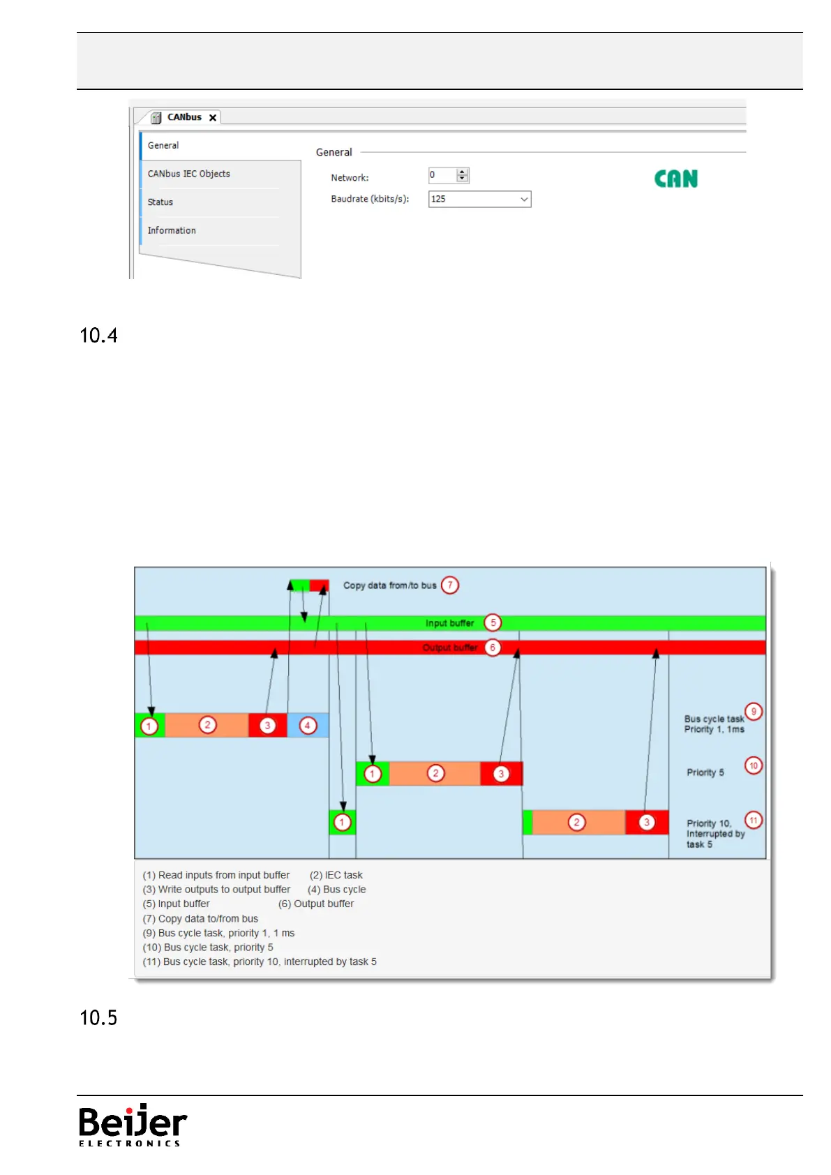
Bus cycle task and I/O updating
As a rule, for each IEC task the used input data is read at the start of each task (1) and the written
output data is transferred to the I/O driver at the end of the task (3). The implementation in the I/O
driver is decisive for further transfer of the I/O data. The implementation is therefore responsible for
the timeframe and the specific time when the actual transmission occurs on the respective bus system.
The bus cycle task of the PLC can be defined globally for all fieldbuses in the PLC settings. For some
fieldbuses, however, you can change this independent of the global setting. The task with the shortest
cycle time is used as the bus cycle task (setting: unspecified in the PLC settings). In this task, the
messages are normally transferred on the bus.
Other tasks copy only the I/O data from an internal buffer that is exchanged only with the
physical hardware in the bus cycle task.
Output status in STOP mode
It is always recommended to set all outputs to FALSE in STOP mode in order to prevent a dangerous
situation. This is done by setting the Update IO while in STOP mode parameter.