1 695 301 979 2011-07-16| Beissbarth GmbH
Product description | MS 75 | 23MS 75 | 23 | 23 en
3.6 Description of function
Below are reported the main functions of the listed
components of the MS 75:
R The remote control allows the operator to control
remotely the operations of the MS 75 by means of
the control lever, the selector and the pedal.
R The mandrel assembly permits locking and rotation
of the rim; it is hydraulically driven and it is compo-
sed of the mandrel holding arm and of the locking
flange (with locking jaws).
R The working assembly permits operations of bead
breaking, demounting and mounting of the tire; it is
hydraulically driven and it is composed of: platform,
trolley, working arm with mounting tool and bead
breaking disk (and relative pins), unlocking pedal.
R The electrical-hydraulic system permits starting,
turning off and adjustment of the hydraulic pressure
of the MS 75.
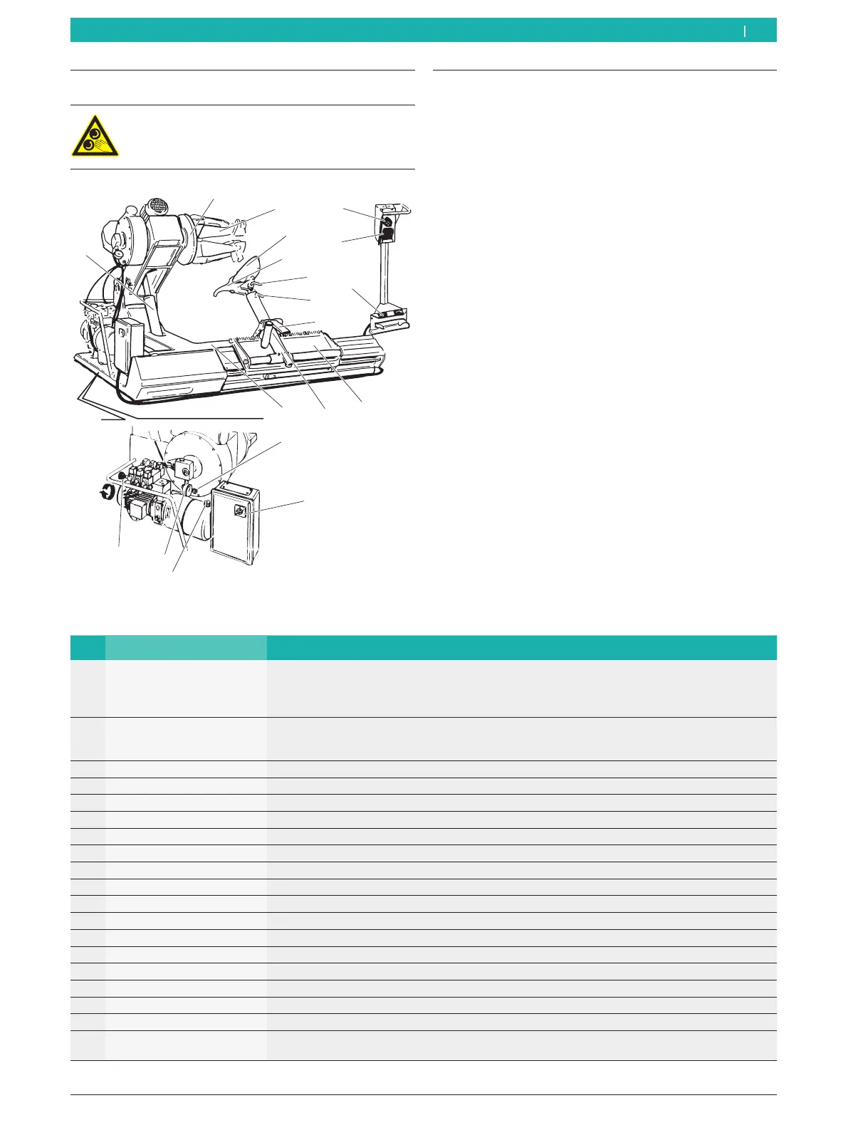
3.5 Description of unit
On the MS 75 there are rotating and moving
parts that could injure fingers and arms.
7
1
2
3
4
5
6
8
9
10
11
12
13
14
15
16
18
17
19
652024-01_Mi
Fig. 1: MS 75
Pos. Name Function
1 Control lever Mandrel- and trolley-holding arm movement:
R Upward movement of the lever lifts the mandrel-holding arm.
R Downward movement of the lever lowers the mandrel-holding arm.
R Left and right movements of the lever control trolley translation.
2 Selector Locking flange activation:
R Left movement of the lever opens the jaws of the locking flange.
R Right movement of the lever closes the jaws of the locking flange.
3 Pedal Opening and closing of the locking plate jaws.
4 Mandrel-holding arm Upward and downward movement of the locking flange.
5 Locking flange Hydraulic locking of the rim and clockwise and counter-clockwise rotation.
6 Locking jaw Rim locking (with different fitting possibilities).
7 Platform Positioning of the wheel before and after tire mounting and demounting operations.
8 Trolley Horizontal translation of the working arm.
9 Working arm Positioning of the mounting tool and of the bead breaking disk.
10 Mounting tool Demounting and mounting of the tire
11 Bead breaker disk Bead breaking and ejection of the tire from its seat on the rim.
12 Mounting tool pin Positioning of the mounting tool.
13 Bead breaker disk pin Bead breaking disk positioning.
14 Unlocking pedal Unlocking of the working arm.
15 Main switch
Starting and turning off the MS 75.
16 Oil level indicator
Oil level indication in the MS 75.
17 Hydraulic pressure knob Adjustment of the mandrel working pressure.
18 Hydraulic manometer Indication of the machine hydraulic pressure.
19 Warning light of the gear-
box oil
Indication that the gearbox oil is at its minimum level.
 Loading...