CHAPTER 2. OPERATOR’S CONTROLS AND INSTRUMENTS
Introduction
This chapter details the layout and operation of the controls and instruments in the B40C.
All operator controls and instruments for the machine are located in the cab.
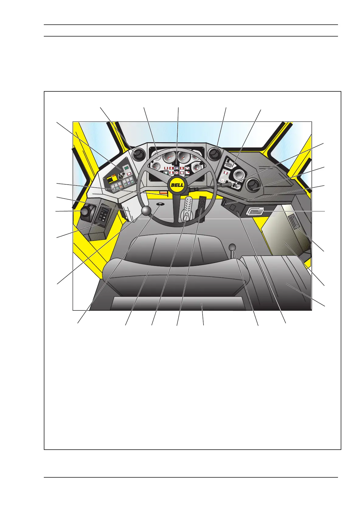
The following figure details the layout of the main controls and instruments in the cab.
870984-01 7
June 1, 1999
S005041
Dia61
0
QUARTZ
HOURS
0
1
10
I
0
0
0
Hobbs
0
1
2
3
4
5
X100
kPa
6
7
8
9
10
L
X
L
WARNING
READTHE
OPERATORS
MANUALBEFORE
CHANGING
DROPBOX
RATIOS
204990
204073
r/min
D
Dia 56
Dia 53
Dia 53
Dia 53
Dia 82
2
x100
REV/MIN
5
10
15
20
25
30
Cels.
50
80
100
120
150
Cels.
40
80
100
120
X100kPa
0
1
23
4
5
!
P
n/min
km/h
10
0
20
30
40
50
60
70
80
0
1/1
1/2
R
N
D
MODE
4
5
8
9
1112131415
17
18
19
20
21
22
23 1
2
3
1016
24 25
6
7
1. Air vent 14. Brake pedal
2. Right side instrument panel 15. Operator’s seat
3. Lights, indicator and horn control lever 16. Controlled traction differential actuating switch
4. Air vent 17. Steering knob
5. Engine stop control 18. Gear shift control
6. Ashtray 19. Park brake/emergency brake lever
7. Air conditioner control panel 20. Distribution box
8. Air conditioner 21. Bonnet catch release lever
9. Passenger seat 22. Left side instrument panel
10. Cigarette lighter 23. Air vent
11. Bin tip control lever 24. Steering wheel
12. Storage compartment 25. Main instrument panel
13. Accelerator pedal
 Loading...