iso165C_D00154_03_M_XXEN/01.2019
12
Connection
5. Connection
5.1 Connection conditions
DANGER
Risk of electric shock!
The terminals HV1 ± / HV2 ± may have nominal voltages measuring up to
600 V. Touching live parts of the system carries the risk of electric shock.
Therefore, the device is only to be operated with mounted and locked
terminal covers.
CAUTION
In order to check that the device is properly connected, a function test must
be carried out before system commissioning by measuring a ground fault
using a suitable resistance.
CAUTION
Terminals T_31_E and T_31_KE must be connected separately to the
chassis.
CAUTION
Risk of injury from sharp-edged terminals!
Handle housing and terminals with care .
CAUTION
In every conductively connected system only one IMD may be connected.
When performing insulation and dielectric tests on the system, the IMD
must be disconnected by opening the HV relays for the duration of the test.
When a monitored AC system contains galvanically coupled DC circuits,
the following applies: an insulation fault can only be accurately detected if
a minimum current of > 10 mA flows through the rectifier valves.
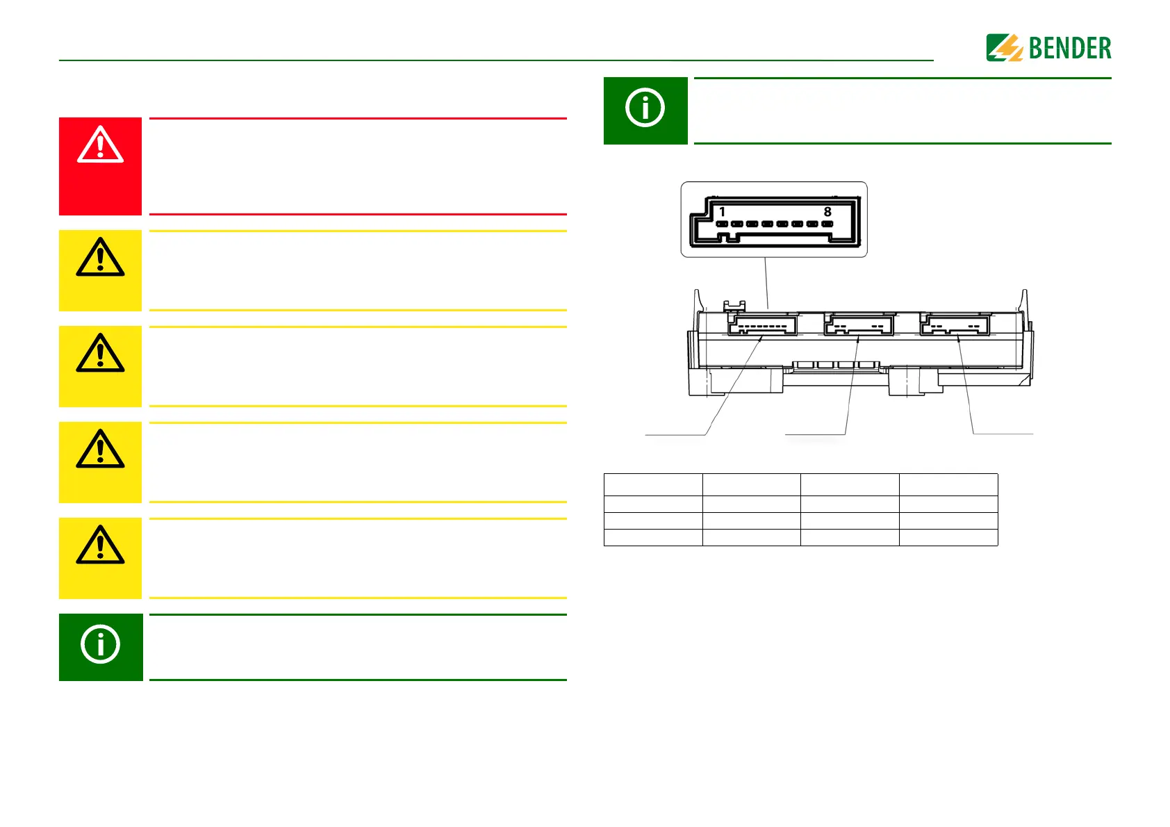
5.2 Connectivity
*) Please refer to "Data" on page 26 for detailed connector information.
The wiring should be carried out in a way that prevents a short circuit from
happening.
Connector*) Type Code Colour
1 1719183-1 A Black
2 1719183-2 B White
3 1719183-3 C Blue
Connector 1
Connector 2
Connector 3