FunctionFunction
iso165C_D00154_03_M_XXEN/01.2019
9
The IMC consists of the HV connectors with HV coupling relays, the measurement circuit
and a microcontroller to analyse the measurement results. It generates internal alarm in-
formation from the measurement results, which is coded to produce the "Alive" signal
mentioned previously. This signal is transmitted in parallel with the measurements and
status information to the VIFC and from there over the HS-CAN bus. The IMC is galvani-
cally separated from the car environment.
At initial power on, the ISOMETER® iso165C does not carry out any measurements until
communication between the VIFC and IMC has been established. In addition, the HV cou-
pling relays of the HV1 voltage path are, by default, open and therefore no valid measure-
ment of voltage HV1 and the insulation resistance is possible until these relays are closed
by an external command. Once these conditions have been satisfied, the ISOMETER®
iso165C can immediately start measuring voltages HV1, HV2 and the insulation resist-
ance.
In the ISOMETER® iso165C-1, however, the HV coupling relays of the HV1 voltage path
are automatically closed at power on.
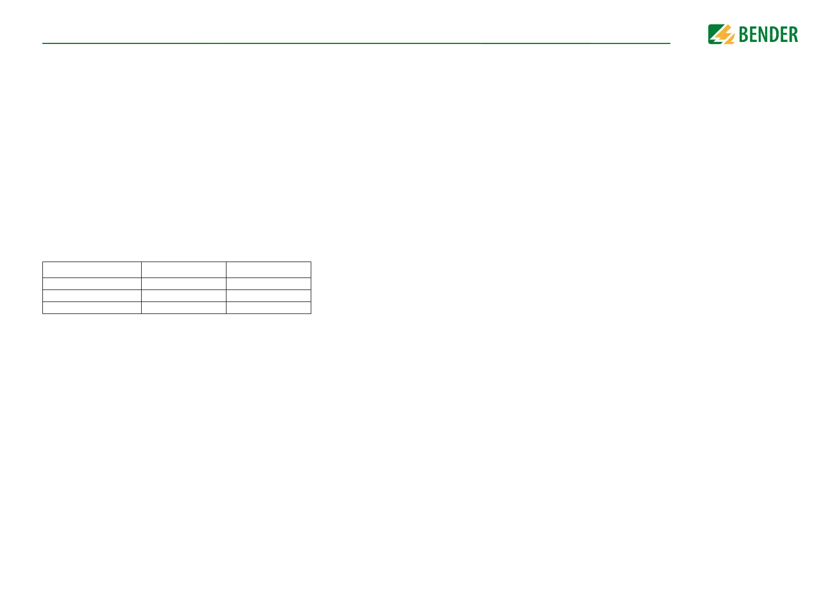
The initial measurement values after power up are:
The ISOMETER® generates a pulsed measuring voltage that is superimposed on the IT sys-
tem by terminals T_31_E/KE (chassis). Because the connection between the terminals E/
KE and the chassis ground (T_31) is continuously monitored, it is necessary to install two
separated conductors from terminals T_31_E/KE to chassis ground.
3.4 Self test
To optimize the start-up time, the ISOMETER® does not automatically execute a self test
during boot up. Instead the execution of a self test is the responsibility of the external su-
pervising system and has to be triggered via the CAN interface. A self test must be re-
quested and can only be carried out when the coupling relays are open. The self test can
be long (approximately 10 s) or short (approximately 1-2 s), and during this time the
ISOMETER® is not able to perform insulation monitoring.
HV relays open HV relays closed
Insulation resistance 50,000 kΩ Value in kΩ
Voltage of HV1 0V Value in V
Voltage of HV2 Value in V Value in V