Connection
iso165C_D00154_03_M_XXEN/01.2019
14
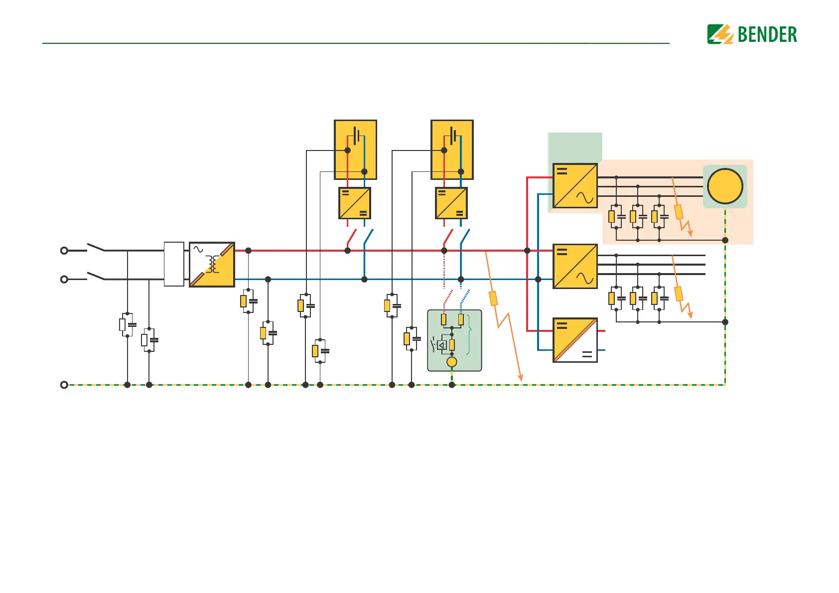
5.3 Typical application
5.3.1 Special application notes
• If terminals HV2 are connected in parallel to terminals HV1 (i.e. a galvanically connected HV system), the measured insulation resistance will be monitored including a +10 % offset
to the real insulation value.
• The HV2 terminals could be used for voltage monitoring at disconnected HV sections (e.g. voltage monitoring of a charging plug).
R
F3
R
F2
R
ISO AC
G
R
Con1
R
F1
R
i
R
m
U
m
R
C
Con1
R
Con2
C
Con2
R
Con3
C
Con3
R
Inv1
R
ISO DC
C
Inv1
R
Inv2
C
Inv2
R
Inv3
C
Inv3
Inverter
RESS 2RESS 1
R
BAT4
C
BAT4
R
BAT3
C
BAT3
R
BAT1
C
BAT1
R
DC2
C
DC2
R
AC2
C
AC2
R
AC1
C
AC1
R
DC1
C
DC1
R
BAT2
C
BAT2
EV Inlet
Electrical Chassis / Protective equipotential bonding
IMD
PFC
M