iso165C_D00154_03_M_XXEN/01.2019
8
Function
3. Function
3.1 Device features
• Insulation monitoring of AC and DC insulation faults for unearthed systems (IT sys-
tems) from 0 V…600 V peak
• Power supply for all internal voltages
• Continuous measurement of insulation resistance from 0 Ω…50 MΩ
• Response time of
≤
20 s for measured insulation resistance (using Direct Current
Pulse (DCP))
• Automatic adaptation to the existing system leakage capacitance (
≤
1 μF)
• Detection of ground faults and lost ground line
• Measurement of a second voltage
• The device works when:
• HV is unstable
• HV is powered off
• There are symmetric or asymmetric insulation faults
• Faults exist between HV lines and the supply voltage
• Galvanic insulation of all signals from the HV side
• HV coupled network
• CAN bus interface
• Light weight: < 220 g (including housing and connection frame)
• iso165C-1 only: The iso165C-1 variant features Error and Warning signals on the
separated high-side driver
3.2 Product description
The ISOMETER® monitors the insulation resistance between the active HV components of
an electrical drive system (U
n
= DC 0 V…600 V) and the reference earth (chassis ground).
The patented measurement technology is used to monitor the condition of the insulation
on the DC side as well as on the AC motor side of the electrical drive system.
The ISOMETER® is assembled with three connectors. To achieve internal galvanic separa-
tion, connector 1 is connected to low-voltage (LV) areas and connectors 2 and 3 are con-
nected to the HV areas in the car environment.
Due to its space saving design and optimized measurement technology, the device is op-
timized for use in hybrid or fully electric vehicles. The device meets the increased auto-
motive requirements with regard to environmental conditions (e.g. temperatures and
vibration, EMC). The ISOMETER® CAN bus interface allows it to integrate seamlessly into
an existing CAN environment.
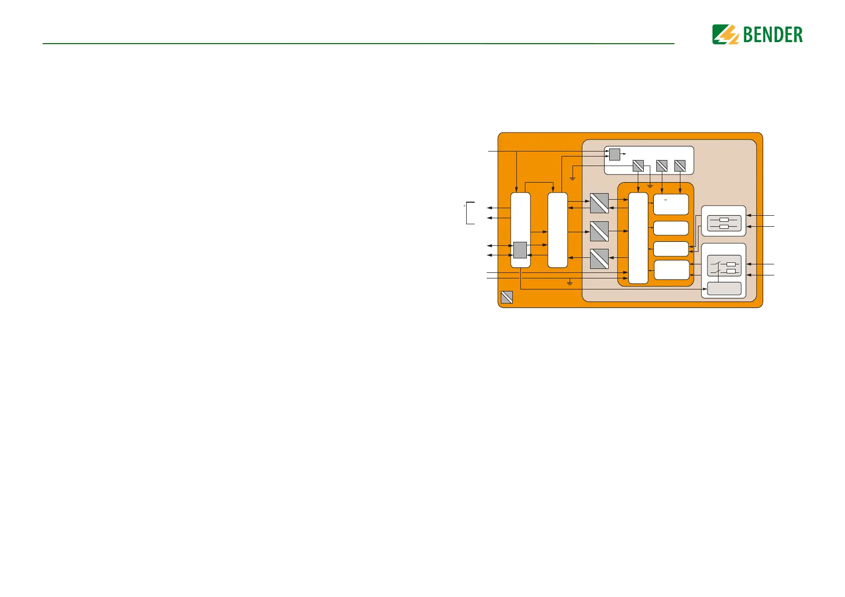
3.3 Function description
The ISOMETER® iso165C and iso165C-1 consist of two main components, the Vehicle In-
terface Controller (VIFC) and the Insulation Monitoring Controller (IMC). The VIFC consists
of a microcontroller with a UART communication interface that translates and forwards
requests from the HS-CAN bus transparently to the IMC. The corresponding IMC respons-
es are returned to the requesting instance via the HS-CAN bus. The VIFC supervises the
running state of the IMC via a signal known as "Alive", and internally and cyclically re-
quests the insulation value and the running state of the IMC. The results are cyclically sent
as an informal message via the HS-CAN bus.
IMC
HV 2
HV 1
Power supply
VIFC
SBC
+12 V -12 V+5 V
HV relays
HV Access
VCC_2
Reset
Alive
Tx
Rx
Pulse
generator
Filter
stage 2
Filter
stage 1
+ 40 V
measurement
power supply
Reset
INH
T_30
VCC_1
CAN
Phy
HS_CAN_H
HS_CAN_L
GND_ISO
GNDD
C
T_31_KE
C
T_31_E
GNDD
HV_2_POS
HV_2_NEG
HV_1_POS
HV_1_NEG
iso165
Galvanic isolation
Error
Warning
ISOMETER
iso165C-1
only
R