8 iso685-x_D00022_12_Q_INTE/12.2023
ISOMETER® iso685…
U
S
U
n
L
L
N
3(N)AC
U
S
U
n
L
L
AC
U
S
U
n
L
*
U
n > 690
V => F 2A
*
*
DC
U
S
IT-System
AGH xxxx
U
n(IT-System)
>
U
n(isoxx685...)
A2/–A1/+
Connect AGH…
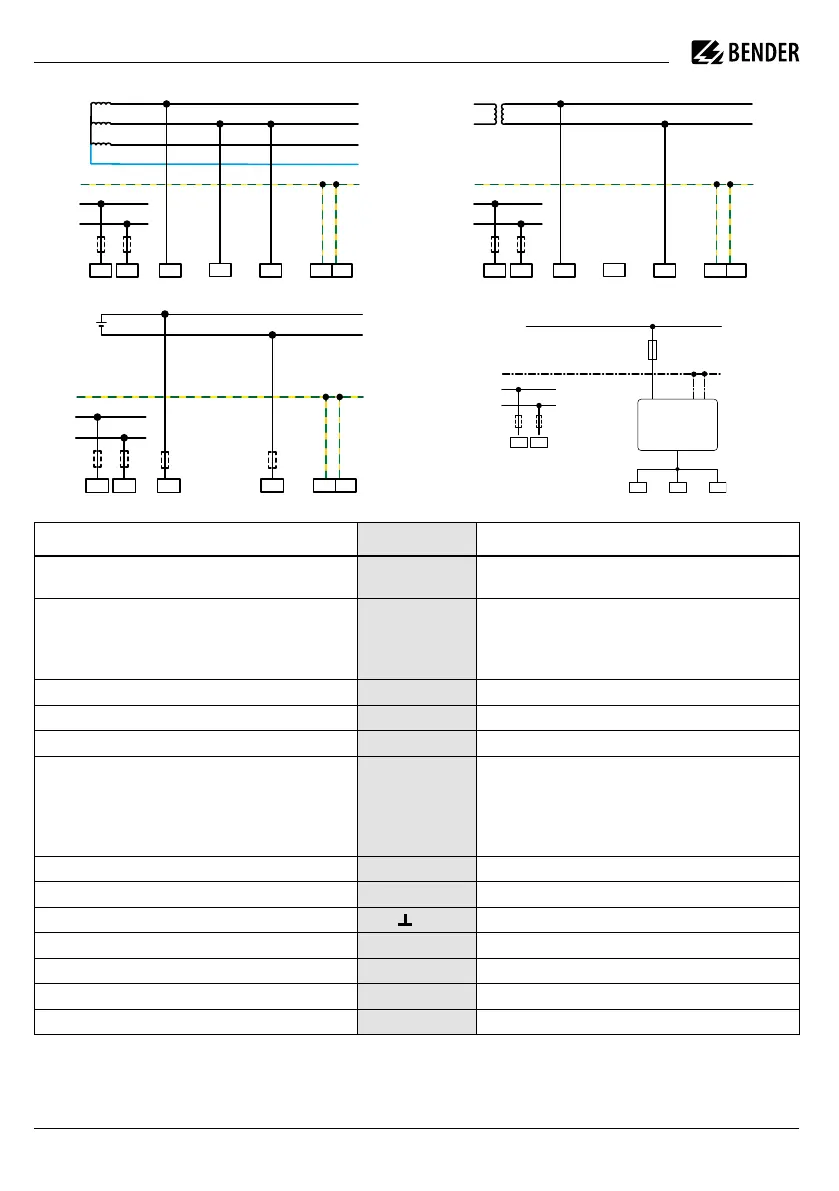
Legend to terminal diagrams
i
** Provide line protection! According to DIN VDE
0100-430, a line protection shall be provided for the
supply voltage
Anschlüsse Klemme/Terminal Connections
Stromversorgung,
U
s
= 24…240 V (50…400Hz)
A1/+ A2/- **
Power supply,
U
s
= 24…240 V (50…400 Hz)
Anschlüsse an das zu überwachende Netz
AC, 0…690 V
AC, 0…600 V für UL-Anwendungen
DC, 0…1000 V
L1/+, L2, L3/-
Connections to the system to be monitored
AC, 0…690 V
AC, 0…600 V für UL applications
DC, 0…1000 V
Anschluss an Erde KE E Connection to ground
Konfigurierbare digitale Eingänge (z. B. Test, Reset, …) I1…I3 (X1) Configurable digital inputs (e.g. Test, Reset,…)
Serielle Schnittstelle RS-485 (BS-Bus) A, B (X1) Serial interface RS-485 (BS bus)
Versorgungsspannung der Ein- und Ausgänge I, Q und M.
Elektr. Überlastschutz. Autom. Abschaltung bei Kurzschluss und
Transiente (rücksetzbar)
Bei Versorgung über ein externes 24-V-Netzteil dürfen A1/+,
A2/- nicht angeschlossen werden.
+ (X1)
Supply voltage of the inputs and outputs I, Q and M.
Electrical overload protection. Automatic shutdown in the event
of a short circuit and transient (resettable).
If the supply is via an external 24 V source, then A1/+, A2/-
must not be connected.
Konfigurierbarer digitaler Ausgang Q1, Q2 (X1) Configurable digital output
Konfigurierbarer analoger Ausgang (z. B. Messinstrument) M+ (X1) Configurable analogue output (e.g. measuring instrument)
Bezugspotential Masse
(X1) Reference potential ground
Ethernet-Anschluss, Webserver, Modbus, IP RJ45 (ETH) Ethernet connector, webserver, modbus, IP
Terminierung für den BS-Bus R Termination for the BS bus
Relais 1 11 12 14 Relay 1
Relais 2 21 22 24 Relay 2
i
** Leitungsschutz vorsehen! Gemäß der DIN VDE
0100-430 ist bei der Versorgungsspannung ein
Leitungsschutz vorzusehen.

 Loading...


