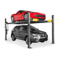
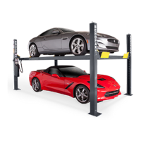
HD-973P Series Multi-Level Parking Lift 36 P/N 5900076 — Rev. B3 — January 2024
With the Cable in place, reinstall the Gusset Sheave and the Cable Lock Pin in Post A.
Push the Threaded end of Lifting Cable A up to and through the Top Cap (at the top of Post A) and
hand tighten it in place with the Nut and Washer you removed earlier.
You only want to hand tighten the Nut at this point so that there is little play in the cabling. We will
securely tighten all four Nuts later in the installation.
Note: The Threaded end of the Lifting Cable A should just go a little bit through the Top Cap. If
it is too long or way too short, you have the wrong Lifting Cable. If it is just a few inches
short, then the Piston on the Hydraulic Cylinder may not have been pulled out far enough.
Make sure the Button end and the unrouted part of Lifting Cable A is under the Large Window,
near the bottom of Post A.
Switching to Lifting Cable C, repeat Steps 1 through 7 for Lifting Cable C, starting at the
Small Window near the bottom of Post C (Power Post).
Once the Threaded end of Lifting Cable C is secured at its Top Cap, return to the Small Window at
the bottom of Post C.
Under the Powerside Runway, move the rest of Lifting Cable C towards where the Side Sheave
goes on the Post C side of the Runway.
Return to the Small Window and reinstall the Cable Sheave.
Make sure Lifting Cable C is correctly positioned in the Cable Sheave in the Small Window.
Position the Button end of Cable C between the Runway and where the Side Sheave will be once
it is reinstalled, and with the Cable in place, reinstall the Side Sheave.
Route the Button end of Cable C towards the Crosstube with Large Windows, where Lifting Cable
A is.
Gather the Button ends of Lifting Cables A and C, making sure to position Lifting Cable A below
Lifting Cable C.
Push Lifting Cables A and C into the Large Window where the Double Cable Sheave goes and pull
the Button ends towards the Pull Box.
With the Cables in place in the Large Window, reinstall the Double Cable Sheave.
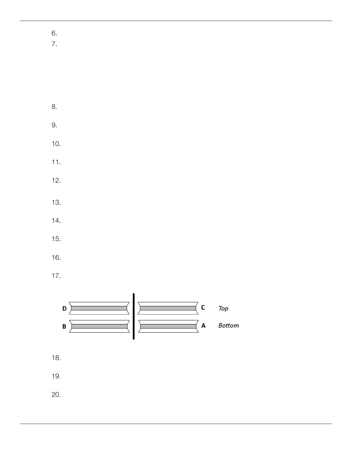
The following drawing shows the Cable/Cable Sheave Pairs in the Large Windows.
Front view of the Crosstube with Large Windows. Not all components shown. Not to scale.
Pull the two Lifting Cables towards the Pull Box and double check that Cable A remains below
Cable C.
Position the Lifting Cables on the correct side of the Pull Box, with the Button ends of both
heading back out of the Pull Box.
With the Cables in place, reinstall the Double Cable Sheave in the Pull Box.
The following drawing shows the Cable/Cable Sheave pairs in the Pull Box.
 Loading...