35
LIFT OPERATION SAFETY (CONT’D)
4. Position vehicle for proper weight distribution arms
under vehicle to allow adapters to contact at the
manufacturer’s recommended pick up points.
5. If the speci c vehicle lift points are not identi ed, or if
the vehicle has additional or uniquely positioned payload,
have a quali ed person calculate the vehicle center of
gravity or have the vehicle center of gravity determined at
a vehicle scale. Load the vehicle with the enter of gravity
midway between adapters.
6. Push the RAISE button or rotate the control switch on
the power unit.
7. Stop before making contact with vehicle. Check arm
restraint pins for engagement. If required, slightly move
arm to allow restraint gear and pawl to mesh. DO NOT
hammer arm restraint pin down as this will damage the
restraint gear teeth.
8. Raise vehicle until tires clear the oor.
9. Stop and check adapters for secure contact at vehicle
manufacturer’s recommended lift points.
WARNING!
MANY SPECIALTY OR MODIFIED VEHICLES CANNOT
BE RAISED ON A TWO-POST FRAME ENGAGING LIFT.
CONTACT VEHICLE MANUFACTURER FOR RAISING
OR JACKING DETAILS.
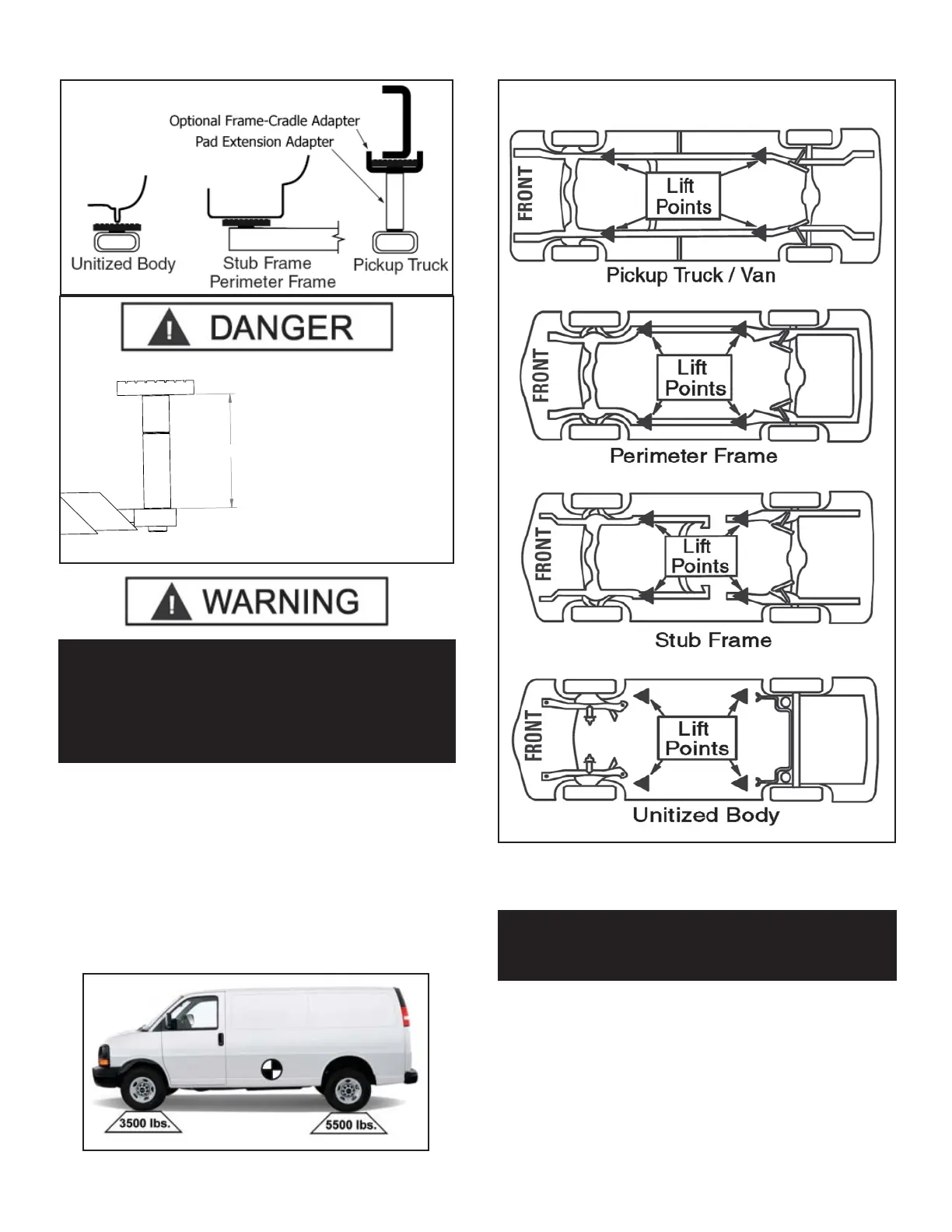
Fig. 19.2
9" MAXIMUM
Fig. 19.3
Never exceed 9” of lift
adapter height by any
combination of adapters.
Failure to comply can
result in serious damage,
personal injury, or death.
TYPICAL LIFTING POINTS
NOTE:
ALLOW (2) SECONDS BETWEEN MOTOR STARTS.
FAILURE TO COMPLY MAY CAUSE MOTOR BURNOUT.